Intersecting structural member and a method for joining same

a structural member and interconnection technology, applied in the field of structural joining, can solve the problems of increasing costs and complexity, difficult to achieve, and creating problems at each intersection of structural members, so as to facilitate the bending of stem engaging tabs, reduce the amount of tab material, and reduce the force required to bend

Inactive Publication Date: 2006-06-20
EDISON WELDING INSTITUTE INC
View PDF19 Cites 3 Cited by
  • Summary
  • Abstract
  • Description
  • Claims
  • Application Information

AI Technical Summary

Benefits of technology

[0025]The seat access region may be formed in any number of configurations. Generally, the seat access region is continuous from the bending axis of the stem engaging tab throughout the length of the stem fixed tab, and may extend any distance from the first structural member base edge into the first predetermined height. Alternatively, the seat access region may only exist beneath the stem engaging tab and not beneath the stem fixed tab. The seat access region provides a working space allowing welding of the first structural member and second structural member to the skin panel. Additionally, the seat access region facilitates the bending of the stem engaging tab in installations where the skin panel is curved so that the bending of the stem engaging tab is not prematurely limited by the curvature of the skin panel.
[0026]In any of the embodiments of the intersecting structural member, the first structural member and the

Problems solved by technology

However, a problem is created at each intersection of these structural members.
It has the disadvantage of requiring very close manufacturing and assembly tolerances, and careful craftsmanship in assembly, all of which increase costs and complexity, and are especially difficult to achieve in shipbuilding or other applications where large components are being fabricated.
This loose fit makes it relatively difficult to close the gap between the structural members, and an additional piece or pieces, called a collar, is traditionally fixed around the aperture to secure the members and close the gap.
It has the disadvantage of requiring a thi

Method used


Image

  • Intersecting structural member and a method for joining same
  • Intersecting structural member and a method for joining same
  • Intersecting structural member and a method for joining same

Examples


Embodiment Construction

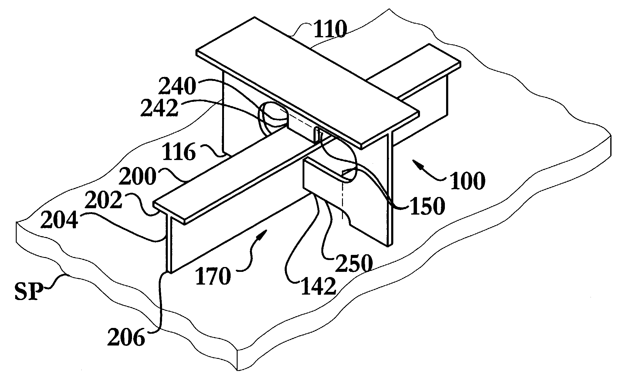
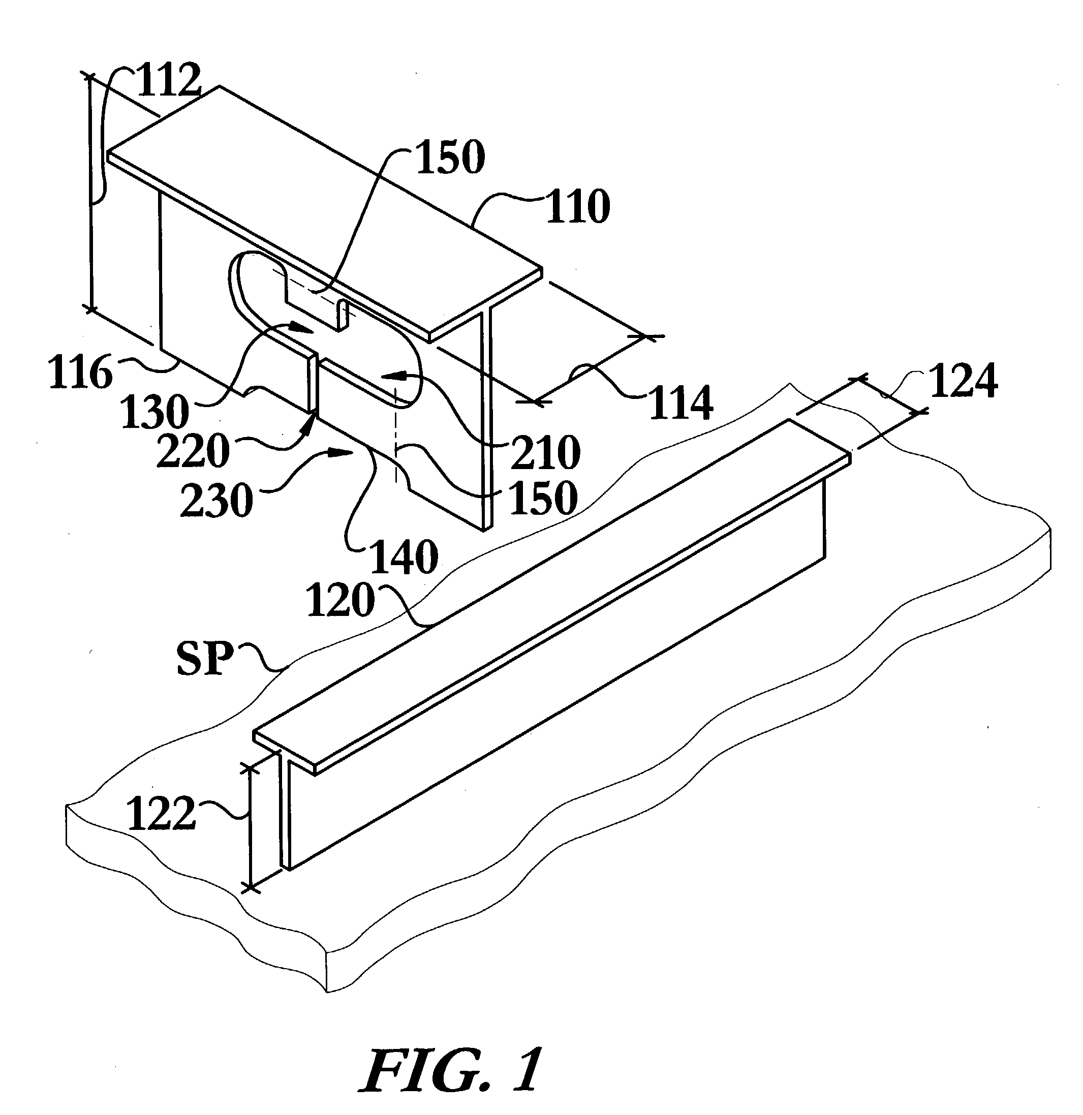
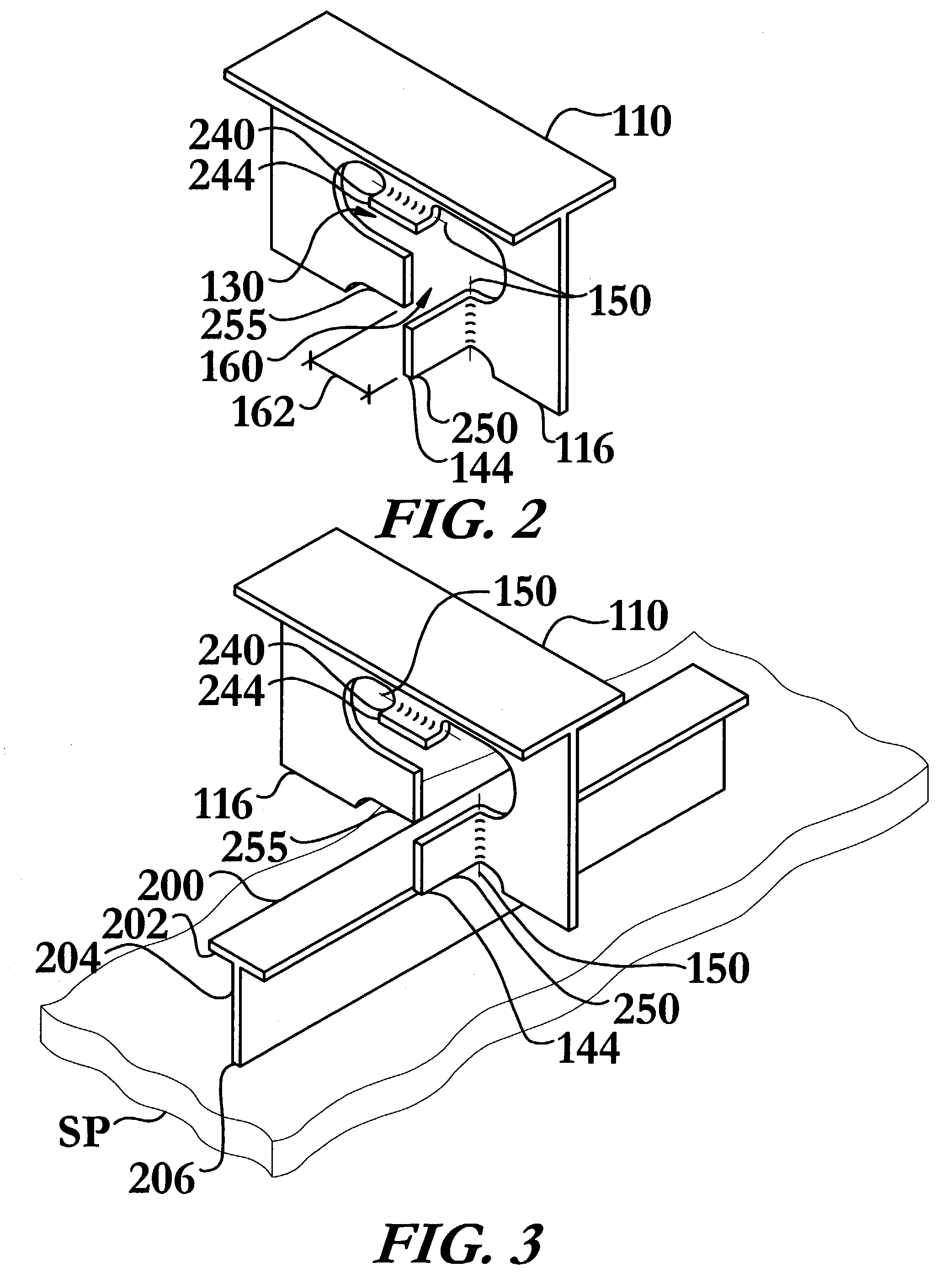
[0044]The intersecting structural member and method of joining same of the instant invention enables a significant advance in the state of the art. The preferred embodiments of the apparatus accomplish this by new and novel arrangements of elements and methods that are configured in unique and novel ways and which demonstrate previously unavailable but preferred and desirable capabilities. In particular, the instant invention's use of a keyway and at least one bendable tab replaces the plurality of welding collars needed in prior art methods, as illustrated in FIG. 6, to effectively join structural members, when one member passes through a non-tight aperture in another structural member.

[0045]The detailed description set forth below in connection with the drawings is intended merely as a description of the presently preferred embodiments of the invention, and is not intended to represent the only form in which the present invention may be constructed or utilized. The description set...


PUM


Abstract

An intersecting structural member, and a method for assembling the same, allowing continuous structural members to intersect while also allowing one edge of each of the structural members to be bonded to a skin panel. A first structural member is provided with at least one bendable tab that allows an ingress area in the first member to be opened to permit the passage of a second structural member. The at least one bendable tab may optionally be designed in various shapes, with or without material reducing regions, may then be closed, interlocking the members and producing the intersecting structural member. This structure and method may be used to eliminate the need for welding collars around the member intersections, reducing labor, materials, weight, complexity of joining, and improving resistance to metal fatigue at the intersections.

Description

STATEMENT REGARDING FEDERALLY SPONSORED RESEARCH OR DEVELOPMENT[0001]This invention was made with government support under Contract No. N00140-96-C-0188, Navy Joining Center Project No. TDL01-06 awarded by the Office of Naval Research (ONR) and Contract N00014-02-C-0106, Navy Joining Center Clin 04, awarded by the Office of Naval Research (ONR). The government has certain rights in the invention.TECHNICAL FIELD[0002]The present invention relates to the field of structural joining; particularly, to a method of joining two structural members, when both members run continuously across at least one intersection.BACKGROUND OF THE INVENTION[0003]Ironworkers and structural assembly persons have long recognized the need for an intersecting structural member that allows some degree of flexibility in assembly, while reducing the additional time spent securing the structural members created by the desired flexibility in assembly. Such long-felt needs have been particularly prevalent in the fie...

Claims


Application Information

Patent Timeline
IPC IPC(8): E04C2/42B63B9/06
CPCB63B3/26
Inventor HOLDREN, RICHARD L.
Owner EDISON WELDING INSTITUTE INC
Why Eureka
Try Eureka