Flow velocity measuring device

a flow velocity and measuring device technology, applied in the direction of liquid/fluent solid measurement, volume metering, instruments, etc., can solve the problems of device limited in the applicable range, increased fan in revolutions, and accuracy degradation, so as to achieve efficient separation of dust and dirt and accurately measure the flow velocity of fluid

Active Publication Date: 2006-06-20
ORMON CORP
View PDF3 Cites 5 Cited by
  • Summary
  • Abstract
  • Description
  • Claims
  • Application Information

AI Technical Summary

Benefits of technology

[0006]Hereupon, it is an object of the invention to provide a flow velocity measuring device capable of conducting a fluid to a sensor element after removal of dust and dirt contained in the fluid to enable accurately measuring the flow velocity of the fluid even when the fluid is low in flow velocity and the device is mounted in any direction.
[0008]With this construction, when the flow velocity measuring device is placed in a fluid flow, a fluid is introduced from the introduction passage to the inner space by the fluid flow and the fluid flows along the curved wall surface of the internal space to be discharged from the discharge passage. At this time, dust and dirt contained in the fluid is locally distributed near the wall surface trying to go straight according to a law of inertia, so that a pure fluid with less dust and dirt is obtained in a region distant from the wall surface of the internal space. The pure fluid can be taken out from the internal space without disturbing a flow of the fluid along the wall surface from the branch passage provided at substantially right angle to a direction along the introduction passage, the discharge passage, and the wall surface connecting between the both passages. Since the flow velocity of the pure fluid is dependent upon the flow velocity of a fluid outside the flow velocity measuring device, the flow velocity of a fluid outside can be found by measuring the flow velocity of the pure fluid with the sensor element. Also, since inertia of dust and dirt can be caused by largely bending a direction, in which a fluid flows along the wall surface, to act, dust and dirt is separated even when the flow velocity of the fluid is small, thus enabling measurement of the flow velocity.
[0010]In this manner, when the internal spaces are connected together in series, it is possible to surely remove dust and dirt from a fluid fed to the sensor element. Even with the internal spaces connected together in parallel, the internal spaces are individually made small provided that the flow velocities in the respective internal spaces are made equal to the flow velocity in the case of the internal space being single, and so a radius of curvature becomes small, so that the effect of separation of dust and dirt owing to inertia is heightened. Also, even when one of the internal spaces or any flow passage connected to the internal space is plugged, a path extending through the other internal spaces functions, so that measurement of flow velocity can be done by adjustment of sensitivity. Also, depending upon the positional relationship between the branch passages, through which a pure air is taken out from the internal spaces, and the discharge passages, through which dust and dirt are carried out, in particular, when the discharge passages are positioned above openings of the branch passages, a part of dust and dirt falls in some cases into the fluid, which is separated by gravitation from flows leading to the discharge passages and taken out into the branch passages. When the plurality of internal spaces are connected with directions of the branch passages being changed, and / or arranged with directions of the branch passages being changed, preferably the branch passages in directions different by 90° or more, more preferably 180°, the discharge passage is not positioned above the opening of the branch passage in at least one of the internal spaces, so that it is possible to optimally perform separation of dust and dirt.
[0016]With this construction, the groove provided on the intermediate plate is closed by the circuit substrate provided with an electronic circuit for the sensor element to configure the second layer flow passage, so that the number of parts is decreased and the construction is made simple. Also, the construction is made simple by making the first layer substrate integral with that structure, which accommodates therein the whole device.
[0022]By projecting the opening of the branch passage into the internal space, dust and dirt in a fluid is hard to enter into the through-hole by gravitation even when the flow velocity measuring device is mounted with the intermediate plate disposed under. Also, by making the internal spaces cylindrical-shaped, flows of a fluid describe a circle, so that separation of dust and dirt is efficient.
[0023]As described above, for a fluid at low flow velocity and even when the device is mounted in any direction, it is possible according to the invention to remove dust and dirt in a fluid to conduct the fluid to a sensor element to accurately measure the flow velocity of the fluid over a long term.

Problems solved by technology

With electronic equipment such as personal computers cooled by a cooling fan, etc., reduction in air volume due to plugging of a filter incurs a decrease in cooling capacity to cause a fear that hindrance is generated in the function of the equipment, and so a flow velocity measuring device is used to monitor the wind velocity at all times so that when air volume is decreased, a fan is increased in revolutions and an alarm is given to a user.
However, there is caused a problem that when conventional flow velocity measuring devices are used over a long term, dust and dirt in an air adhere to and accumulate on a sensor element to cause degradation in accuracy.
However, the device disclosed in JP-A-11-166720 has a disadvantage that when the flow velocity of an air flow is low, dust and dirt are insufficient in inertia to be adequately separated, and involves a problem that when mounted horizontally, dust and dirt once caught by the trap wall positioned above the flow passage fall again in the air flow to be carried to the sensor element, so that the device is limited in an applicable range.

Method used


Image

  • Flow velocity measuring device
  • Flow velocity measuring device
  • Flow velocity measuring device

Examples


Embodiment Construction

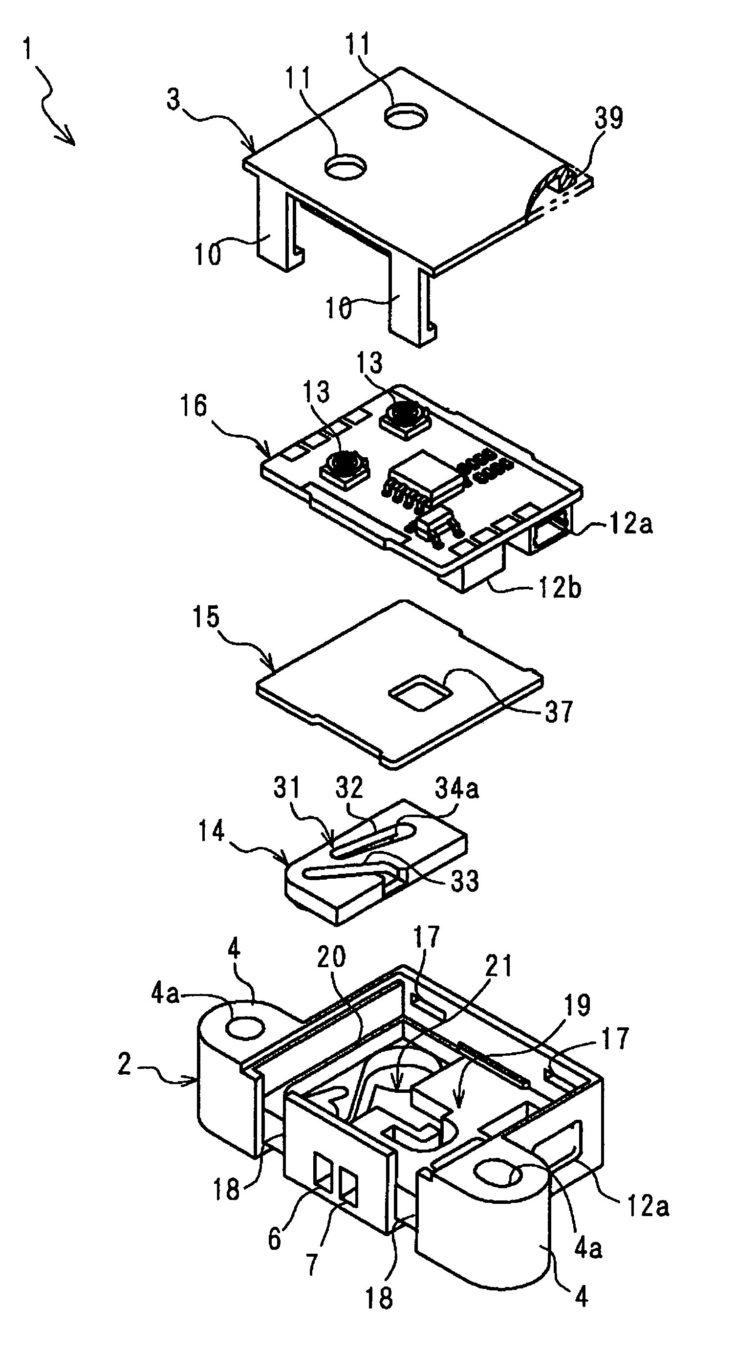
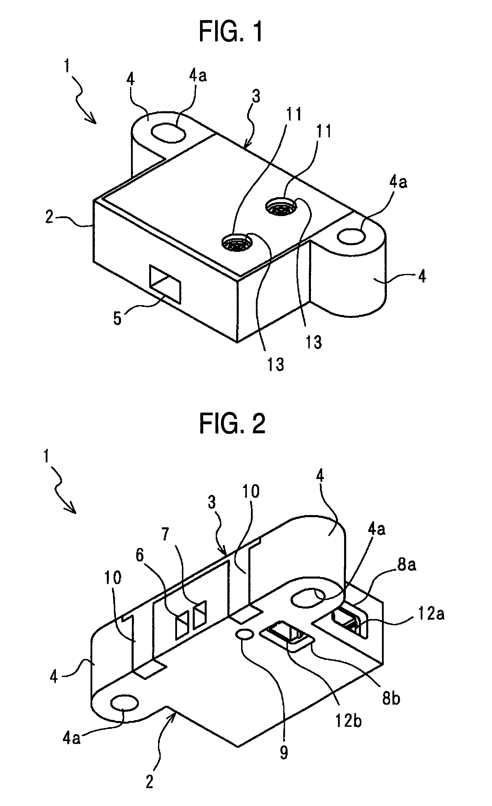
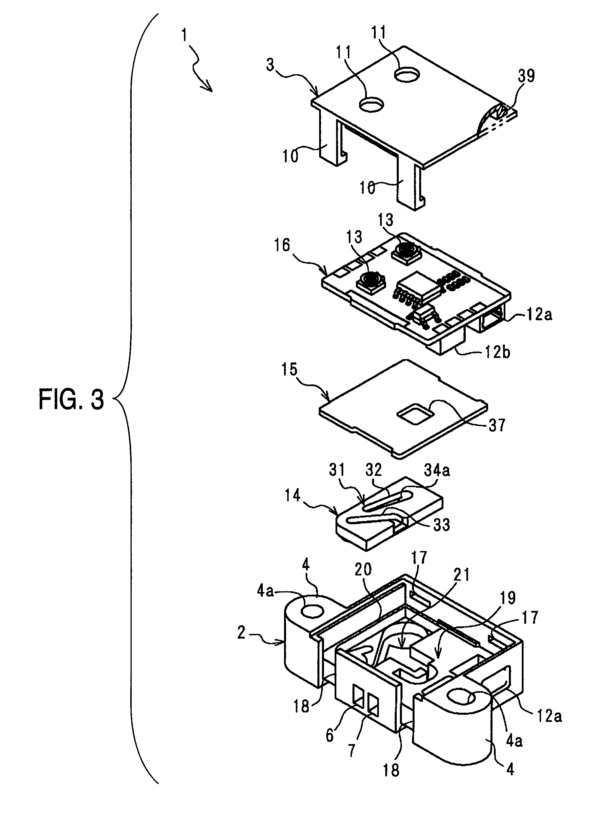
[0036]FIGS. 1 and 2, respectively, are views showing a flow velocity measuring device 1, according to an embodiment of the invention, as viewed from obliquely upwardly of the front and obliquely downwardly of the back. The flow velocity measuring device 1 mainly serves to measure the flow velocity of an air, and comprises a housing 2 including a first layer substrate and a cover 3. The housing 2 is shaped to provide overhangs 4 on sides of a rectangular solid, the overhangs having screw holes 4a for fixation of the flow velocity measuring device 1 to a location of measurement, the housing including an intake port 5 on a front surface thereof for taking in a flow of an air being measured, a first discharge port 6 and a second discharge port 7 on a back surface thereof, a first connector hole 8a on a side thereof, and a second connector hole 8b and a positioning hole 9 on a bottom surface thereof. The cover 3 is mounted on an upper surface of the housing 2 by means of two hooks 10 for...


PUM


Abstract

A flow velocity measuring device is able to conduct a fluid to a sensor element after removal of dust and dirt contained in the fluid to accurately measure the flow velocity of the fluid even when the fluid is low in flow velocity and the device is mounted in any direction. A flow passage is formed by internal spaces, which have curved wall surfaces, introduction passages connected to the internal spaces at one ends of the wall surfaces tangentially to the wall surfaces, discharge passages connected to the internal spaces at the other ends of the wall surfaces tangentially to the wall surfaces, and branch discharge passages connected to the internal spaces at substantially right angle to a direction, in which the wall surfaces are curved, and a sensor element is arranged in the branch passage or a flow passage connected to the branch passage.

Description

BACKGROUND OF THE INVENTION[0001]1. Field of the Invention[0002]The present invention relates to a flow velocity measuring device.[0003]2. Description of Related Art[0004]With electronic equipment such as personal computers cooled by a cooling fan, etc., reduction in air volume due to plugging of a filter incurs a decrease in cooling capacity to cause a fear that hindrance is generated in the function of the equipment, and so a flow velocity measuring device is used to monitor the wind velocity at all times so that when air volume is decreased, a fan is increased in revolutions and an alarm is given to a user. Conventionally, flow velocity measuring devices adopted in such use are constructed to arrange a sensor element in a flow passage to measure the flow velocity of an air. However, there is caused a problem that when conventional flow velocity measuring devices are used over a long term, dust and dirt in an air adhere to and accumulate on a sensor element to cause degradation in...

Claims


Application Information

Patent Timeline
Patent Type & Authority Patents(United States)
IPC IPC(8): G01F1/68G01F1/684G01F5/00G01F15/12G01P5/00G01P5/10G01P5/12
CPCG01F1/6842G01F5/00G01P5/12G01P5/10G01F15/12G01P5/07
Inventor FUJIWARA, TOSHIMITSUNOZOE, SATOSHIUEDA, NAOTSUGU
Owner ORMON CORP
Why Eureka
Try Eureka