Fan penetration feature for in-vehicle testing

a technology for in-vehicle testing and fan penetration, which is applied to non-positive displacement fluid engines, wind motor components, liquid fuel engine components, etc., can solve the problems of limited amount of fan locations achievable, inability to optimize the fan within these parameters, and time-consuming processes, so as to achieve efficient fan performance and reduce the effect of changeover tim

Inactive Publication Date: 2006-06-20
BORGWARNER INC
View PDF12 Cites 13 Cited by
  • Summary
  • Abstract
  • Description
  • Claims
  • Application Information

AI Technical Summary

Benefits of technology

[0007]The present invention provides a method for testing cooling performance characteristics of a fan drive system at various fan penetrations during in-vehicle cooling tests. This feature allows optimal fan penetration positioning within the cooling system to be accomplished in a fraction of the time typically associated with prior art systems that utilize shims to determine optimal fan penetration. Further, the present invention allows quick changeovers without the need to cool down the engine, thereby decreasing changeover time associated with the cooling and subsequent warm-up of the engine back to operating temperatures during these tests. Also, the present invention allows for an infinitely variable fan location relative to the fan clutch assembly, as compared with systems that utilize shims and have a limited amount of potential fan penetration settings, thereby resulting in potentially more efficient fan performance than through the use of shims.
[0008]The present invention provides a fan penetration fixture consisting of a threaded shaft and a locking fan hub design. The fixture is designed to take the place of the fan clutch on a fan drive assembly in the vehicle being tested. The threaded shaft portion of the fixture bolts to the fan hub. The desired fan is then bolted to the locking fan hub portion of the fixture. The lock nut can be positioned at any point along the threaded shaft to achieve a desired fan penetration. The vehicle is then turned on and warmed to operating temperature, wherein the cooling system is then tested for a one or more cooling system performance characteristics. To alter fan penetration, simply loosen the lock nut feature, reposition the fan along the threaded shaft, and retighten the lock nut feature to a new fan penetration, wherein the vehicle is turned on and new measurements taken. The changeover is quick and easy, and may be done without first substantially cooling the vehicle's engine.

Problems solved by technology

This process in time consuming, typically taking up to two or three hours to complete each shim alteration.
Another undesirable feature associated with the use of shims to alter fan penetration is the limited amount of fan locations achievable.
Thus, fan optimization can be compromised within these parameters.

Method used


Image

  • Fan penetration feature for in-vehicle testing
  • Fan penetration feature for in-vehicle testing
  • Fan penetration feature for in-vehicle testing

Examples


Embodiment Construction

[0014]In the following figures the same reference numerals will be used to refer to the same components. In the following description, various operating parameters and components are described for one constructed embodiment. These specific parameters and components are included as examples and are not meant to be limiting.

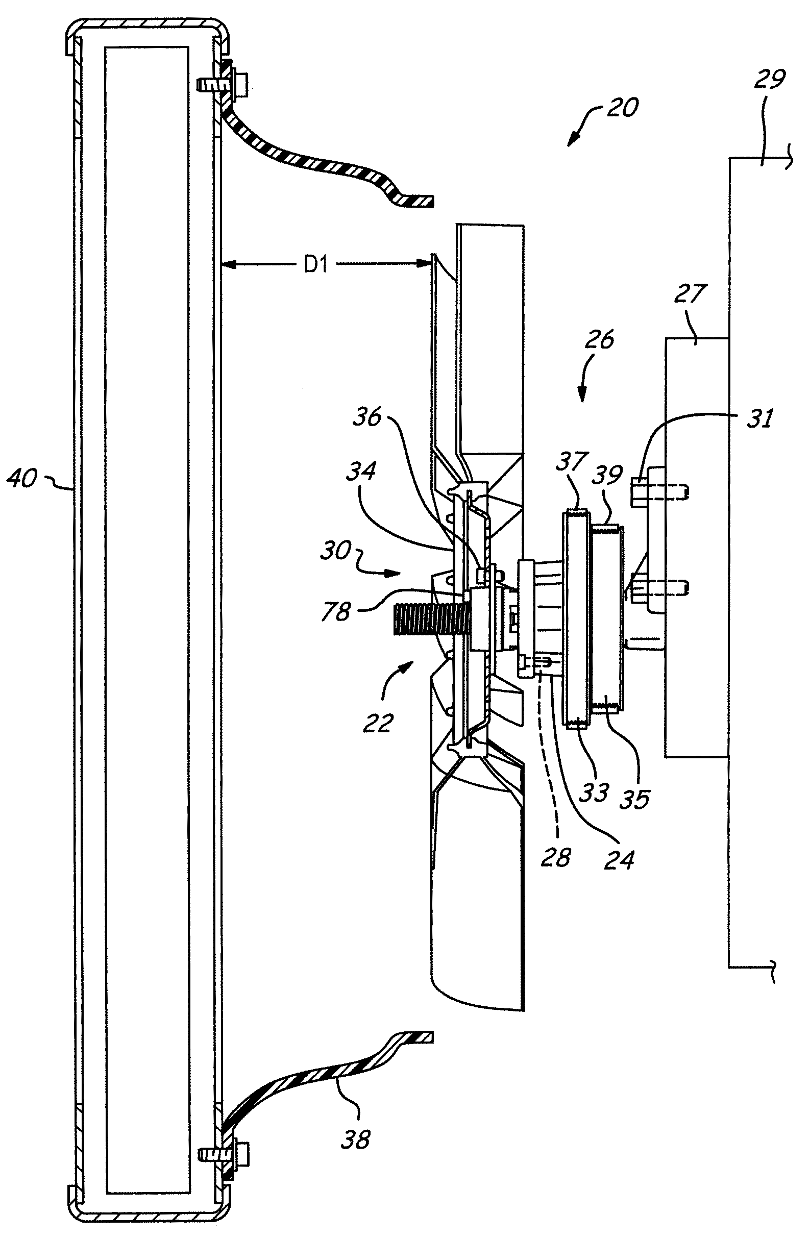
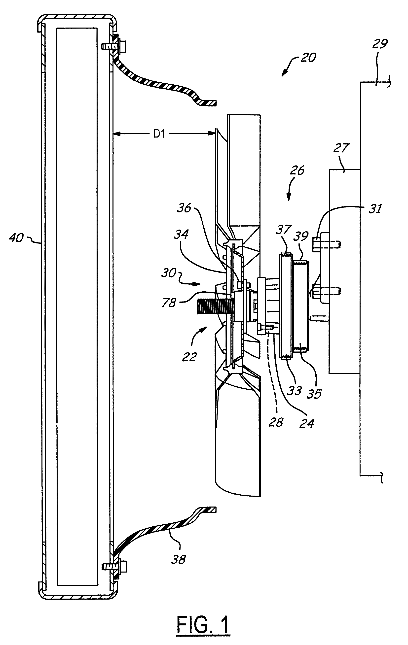
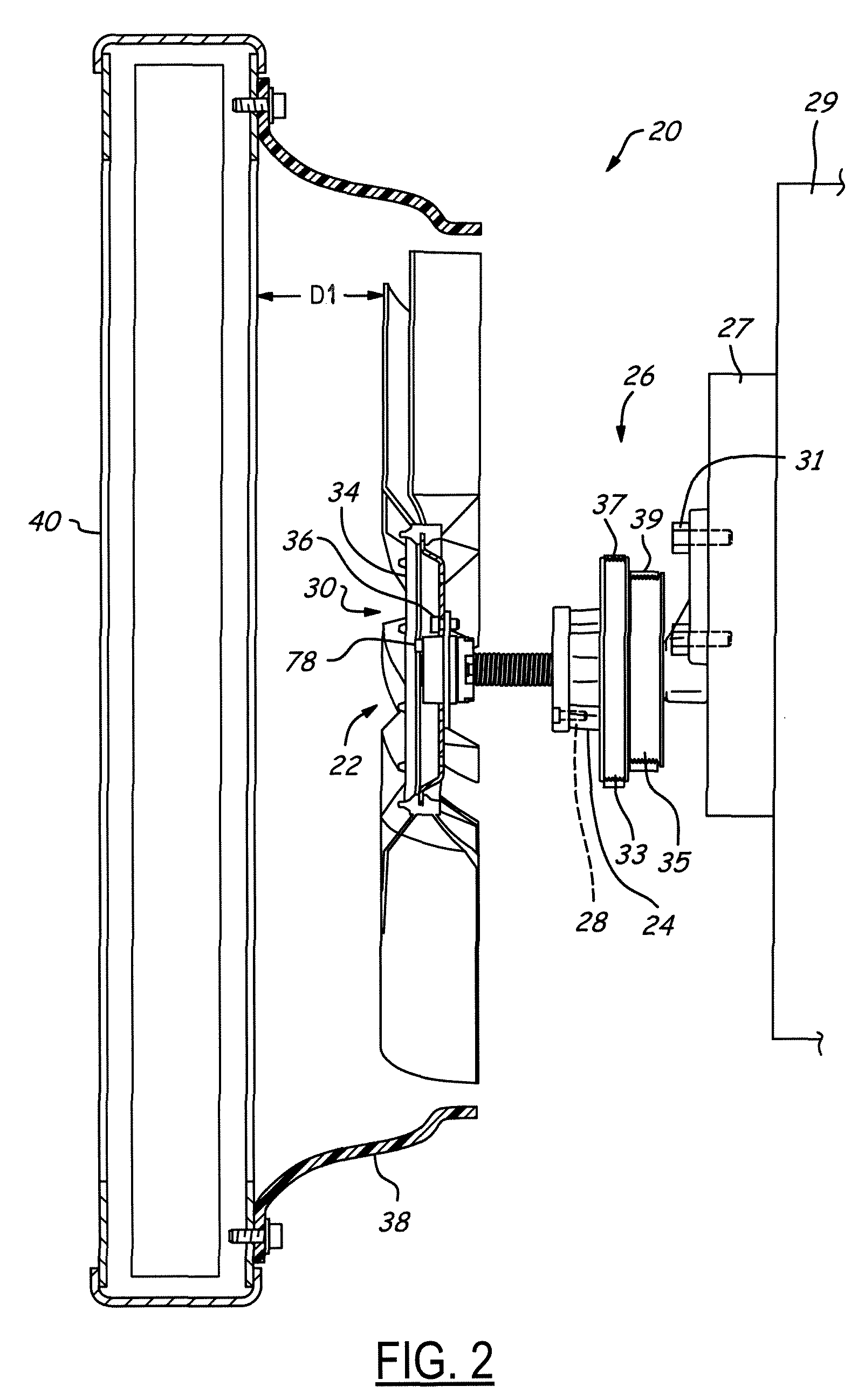
[0015]Referring now to FIGS. 1 and 2, a cooling system 20 is depicted as having a fan penetration fixture 22 secured to a front portion 24 of a fan hub assembly 26 preferably using one or more socket head cap bolts 28. The fan hub assembly 26 is also coupled opposite the fan penetration fixture 22 to the FEAD (Front End Accessory Drive) bracket on the front gear case 27 of the engine 29 preferably using a series of bolts 31. The fan hub assembly 26 also has a crank pulley 33 and accessory pulley 35. A drive belt 37 is coupled to the crank pulley 33 which in turn is mounted to the engine crankshaft (not shown). A second drive belt 39 is coupled to the accessory pull...


PUM


Abstract

A fan penetration fixture consisting of a threaded shaft and a lock nut design. The fixture is designed to take the place of the fan clutch on a fan drive assembly in the vehicle being tested for a desired cooling system performance characteristic at each possible fan penetration. The threaded shaft portion of the fixture bolts to the fan hub. The desired fan is then bolted to the lock nut portion of the fixture. The lock nut can be positioned at any point along the threaded shaft to achieve a desired fan penetration.

Description

BACKGROUND OF INVENTION[0001]The invention relates generally to fan drive systems and more specifically to a fan penetration feature for in-vehicle testing.[0002]In-vehicle testing of fans and fan drives is highly desirable to optimize the cooling performance of the fan on cooling system components, such as a radiator, balanced against other performance factors such a fuel economy and power usage.[0003]In order to obtain optimal performance for an associated fan drive and clutch system, it is desirable to alter the fan penetration within the radiator shroud during in-vehicle testing. Fan penetration, for the purposes of the present invention, is defined as the distance between the fan blades and the radiator. The greater the fan penetration, the smaller the distance between the fan leading edge of the blades and the radiator, and the deeper the fan blades are positioned within a radiator shroud and away from the fan clutch assembly. As the fan is rotated at a fixed rotational speed ...

Claims


Application Information

Patent Timeline
Patent Type & Authority Patents(United States)
IPC IPC(8): B60H1/00F01P5/04F01P5/06F04D29/26
CPCF04D29/263F01P5/06F01P5/04F04D29/052
Inventor TEMBREULL, THOMASSPRYGADA, BENJAMIN
Owner BORGWARNER INC
Why Eureka
Try Eureka