Rail mounting apparatus for electronic device

a technology for mounting apparatuses and electronic devices, which is applied in the direction of machine supports, building scaffolds, other domestic objects, etc., can solve the problems of reducing the available workspace occupied by equipment, inability to place equipment in a desired location, and affecting the stability of the device, so as to achieve the effect of reducing the risk of eye strain, neck strain, and/or cumulative trauma such as carpel tunnel syndrom

Inactive Publication Date: 2006-06-20
INNOVATIVE OFFICE PROD LLC
View PDF15 Cites 90 Cited by
  • Summary
  • Abstract
  • Description
  • Claims
  • Application Information

AI Technical Summary

Benefits of technology

[0014]In an example, the lower mount is secured to the wall mount. In another example, the lower mount is permanently affixed to the wall mount. Alternatively, the lower mount may be slideably received by the pair of elongated

Problems solved by technology

One drawback to these configurations is the reduction in available workspace taken up by the equipment.
Another drawback is the inability to place the equipment in a desired location.
A further drawback is the potential for eye strain, neck strain and / or a cumulative trauma disorder such as carpel tunnel syndrome from poor placement of devices such as monitors and keyboards.
While this may free up workspace, it often places the equipment in an undesirable location.
However, in many cases it is not desirable to tie the extension arm to the workspace itself.
Unfortunately, this design may be unable to manage heavy or bulky loads, e.g., large screen monitors.
However, existing tilter devices may not be fully compatible with heavy and / or bulky equipment, such as large screen monitors.

Method used


Image

  • Rail mounting apparatus for electronic device
  • Rail mounting apparatus for electronic device
  • Rail mounting apparatus for electronic device

Examples


Embodiment Construction

[0029]The aspects, features and advantages of the present invention will be appreciated when considered with reference to the following description of preferred embodiments and accompanying figures. In describing the preferred embodiments of the invention illustrated in the figures, specific terminology will be used for the sake of clarity. However, the invention is not intended to be limited to the specific terms so selected, and it is to be understood that each term selected includes all technical equivalents that operate in a similar manner to accomplish a similar purpose.

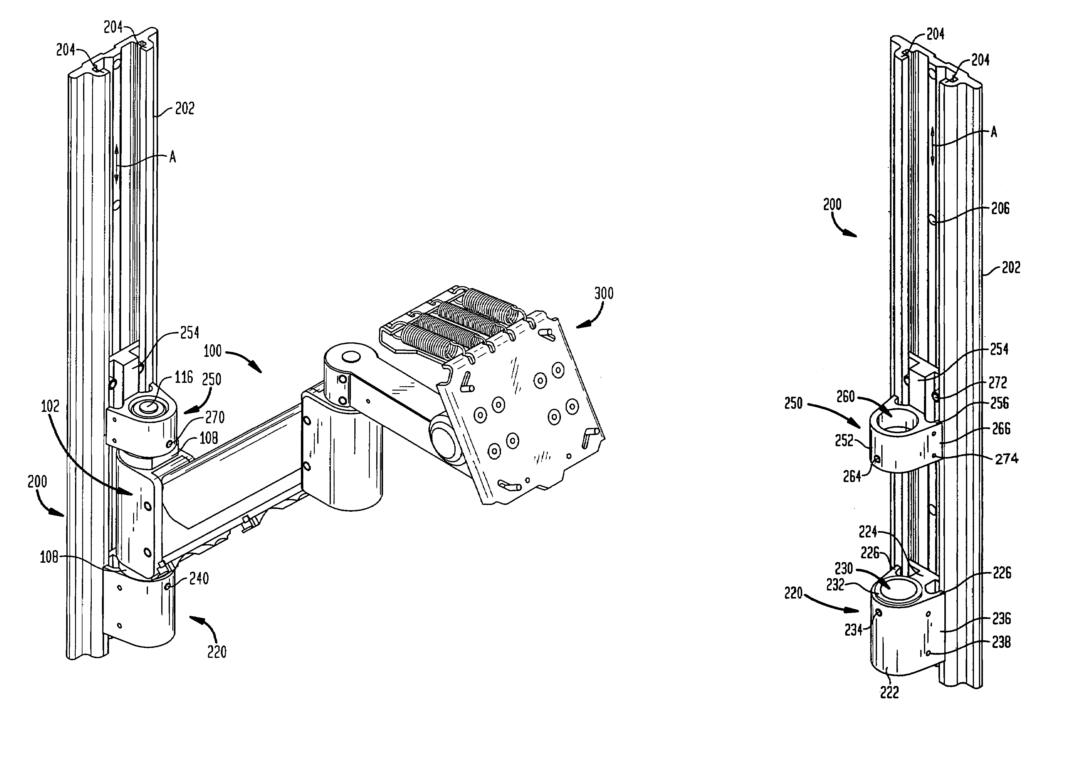
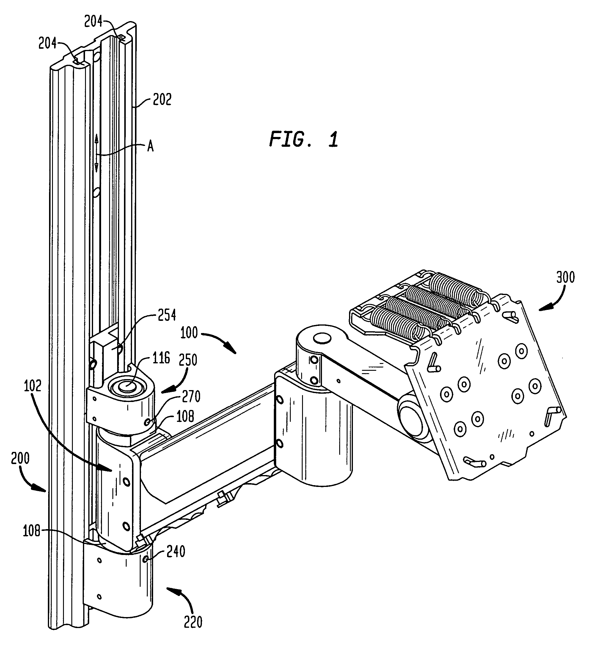
[0030]FIG. 1 illustrates an extension arm 100 engaged at one end to a rail mount 200 and attached to a tiling device 300 at the other end. The rail mount 200 may be affixed to a wall or other substantially flat surface. The features of the rail mount 200 will be explained in more detail below with regard to FIGS. 3–5. The tilting device 300 is adapted to attach to an electronic device, and provides a bias or cou...


PUM


Abstract

A rail mount is provided for positioning an electronic device such as a flat panel display that is mounted to a support arm. The rail mount includes a wall mount and lower and upper mounts received by the wall mount. The wall mount is adapted for attaching to a surface and includes a pair of elongated rails having an axis therebetween. The lower and upper mounts are received within the rails, and each includes a central opening aligned along the axis. An endcap of the support arm is received within the lower and upper mounts and is rotatable about the axis.

Description

BACKGROUND OF THE INVENTION[0001]The present invention relates to a mounting apparatus for positioning electronic devices. More particularly, the present invention relates to a rail mounting apparatus for supporting an electronic device such as a flat panel display mounted on an arm assembly.[0002]In the past people have placed video monitors and other electronic equipment on desks, tabletops, or upon other equipment such as personal computers or workstations. One drawback to these configurations is the reduction in available workspace taken up by the equipment. Another drawback is the inability to place the equipment in a desired location. A further drawback is the potential for eye strain, neck strain and / or a cumulative trauma disorder such as carpel tunnel syndrome from poor placement of devices such as monitors and keyboards.[0003]Different solutions have been provided in order to overcome these obstacles. For example, in one solution, a monitor stand or printer stand elevates ...

Claims


Application Information

Patent Timeline
IPC IPC(8): E04G3/00F16M11/04F16M11/24F16M13/02
CPCF16M11/04F16M11/10F16M11/2014F16M11/24F16M13/02F16M11/2092F16M2200/063F16M2200/04
Inventor WILLIAMS, HOWARD M.
Owner INNOVATIVE OFFICE PROD LLC
Why Eureka
Try Eureka