Horizontal machining center

a horizontal machining center and horizontal technology, applied in the direction of manufacturing tools, transportation and packaging, protection and storage accessories, etc., can solve the problem of large footprint of the whole machining center, and achieve the effect of reducing the size of the machining center and reducing the floor spa

Active Publication Date: 2006-06-20
YAMAZAKI MAZAK KK
View PDF13 Cites 11 Cited by
  • Summary
  • Abstract
  • Description
  • Claims
  • Application Information

AI Technical Summary

Benefits of technology

[0008]The present invention provides a horizontal machining center that is reduced in width and enhanced in maintainability through improvements in structure of a cover for an X-axis slidable surface and in placement of a tool magazine and the cover.
[0011]According to the present invention, the cover provided in a vertical plane can be disposed with one edge thereof passing through the opening formed in the middle of the tool magazine. Therefore, the whole machine can have a reduced size, and the floor space therefore can be reduced.

Problems solved by technology

In addition, the machining center has an automatic tool change unit near the spindle and, thus, has to have a space for accommodating a tool magazine or the like, which leads to a large footprint of the whole machining center.

Method used


Image

  • Horizontal machining center
  • Horizontal machining center
  • Horizontal machining center

Examples


Embodiment Construction

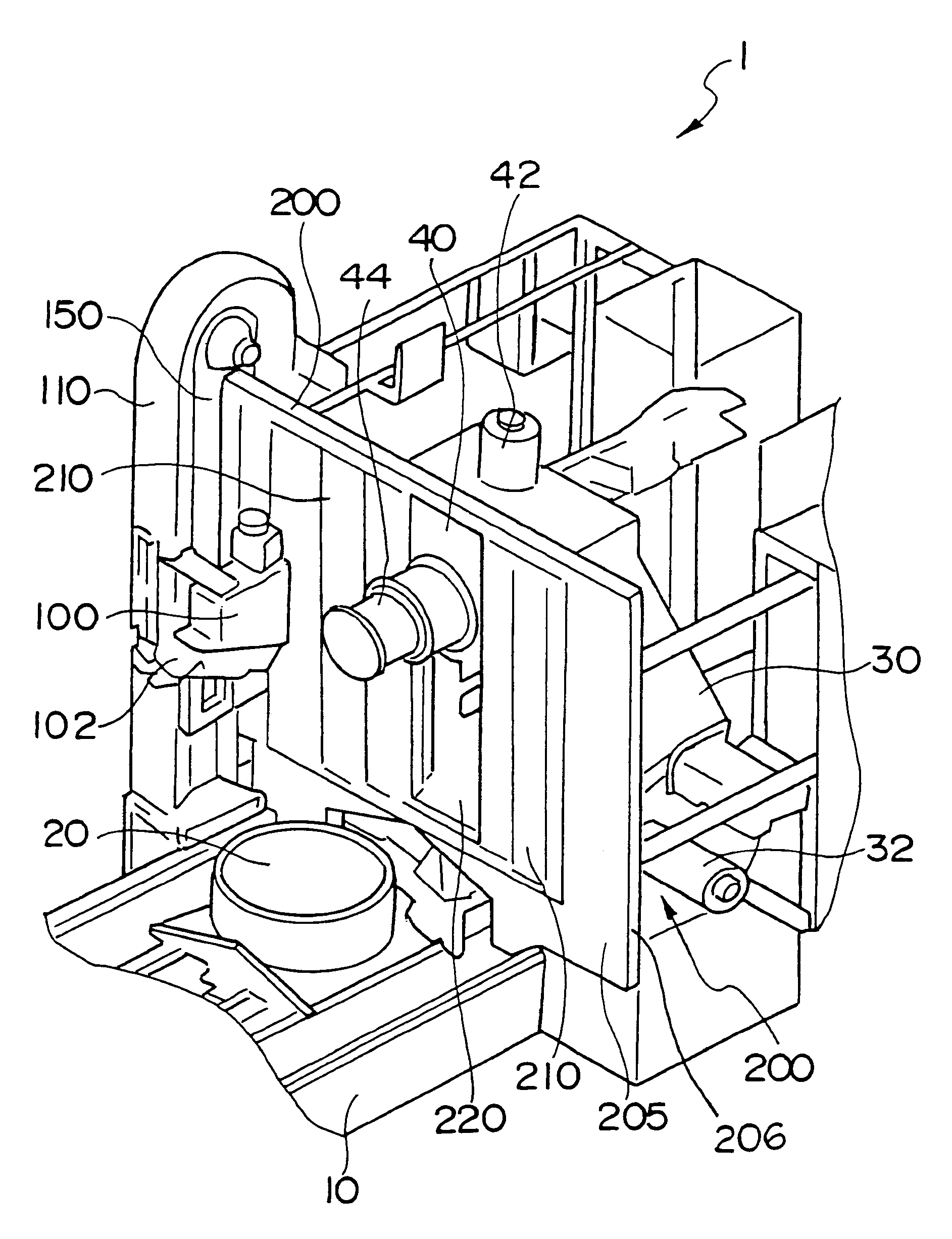
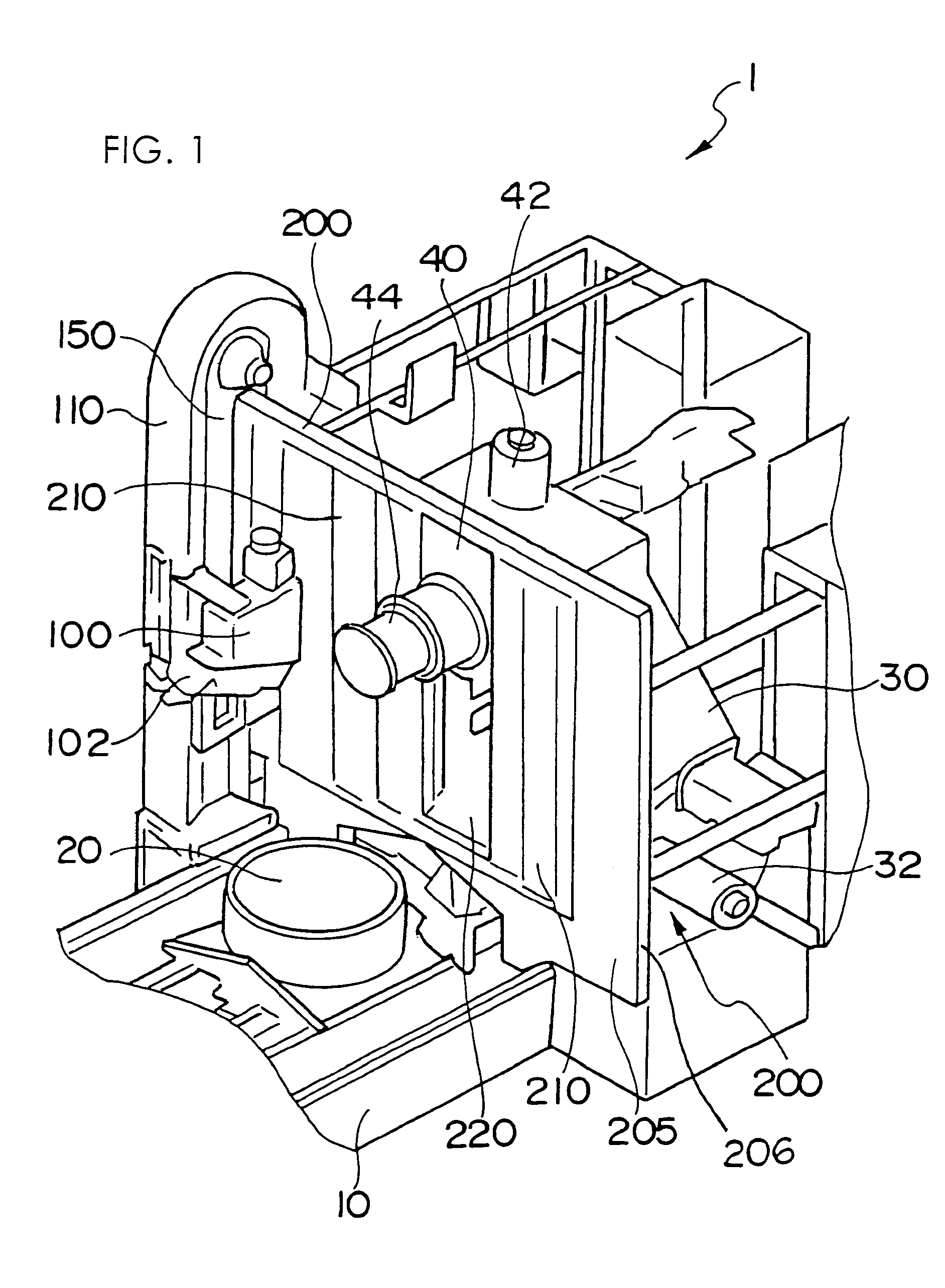
[0017]FIG. 1 is a schematic perspective view of a horizontal machining center according to an embodiment of the present invention.

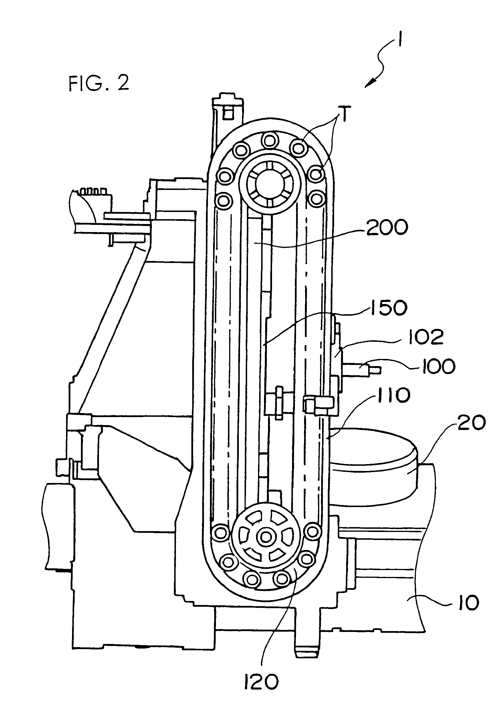
[0018]A horizontal machining center generally denoted by reference numeral 1 has a table 20 on a bed 10, and a workpiece is mounted on the table 20.

[0019]The bed 10 has an X-axis slidable surface (not shown), and a column 30 is mounted on the bed 10 slidably along an X axis. The column 30 is driven by a servo motor 32.

[0020]On the column 30, a spindle stock 40 is supported slidably along a Y axis. The spindle stock 40 is driven along the Y axis by a servo motor 42. A spindle 44 supported by the spindle stock 40 grasps a cutting tool and relatively moves with respect to the table 20 along a Z axis.

[0021]A tool magazine 110 is placed near the bed 10 and the table 20. An automatic tool change unit 100 is mounted between the tool magazine 110 and the spindle 44. The automatic tool change unit 44 is to remove a tool after use from the spindle 44 and inserts a ...


PUM

PropertyMeasurementUnit
widthaaaaaaaaaa
sizeaaaaaaaaaa
movementsaaaaaaaaaa

Abstract

A horizontal machining center 1 has a table 20 on a bed 10. An X-axis slidable surface is provided on the bed 10, and a column 30 is driven by a servo motor 32. A spindle stock 40 is supported on the column 30 and is driven along a Y axis extending in a vertical direction. An automatic tool change unit 100 replaces a tool on a spindle 44 on the spindle stock 40 with a tool in a tool magazine. An X-axis cover 200 provided between the table 20 and the column 30 has a plate-like fixed cover 205 and a pair of slidable covers 210. The fixed cover 205 is disposed with one edge thereof passing through an opening 150 formed in the middle of the tool magazine 110. Structured in this way, the horizontal machining center can have a reduced size.

Description

[0001]The present application is based on and claims priority of Japanese patent application No. 2003-360982 filed on Oct. 21, 2003, the entire contents of which are hereby incorporated by reference.BACKGROUND OF THE INVENTION[0002]1. Field of the Invention[0003]The present invention relates to a horizontal machining center. In particular, the present invention relates to improvements of a cover structure for a slidable section and the placement of a tool magazine of a horizontal machining center.[0004]2. Description of the Related Art[0005]Multitasking machine, such as a horizontal machining center, has a cover for preventing intrusion of chips and cutting fluid into a gap between sliding surfaces during cutting of a workpiece. In addition, the machining center has an automatic tool change unit near the spindle and, thus, has to have a space for accommodating a tool magazine or the like, which leads to a large footprint of the whole machining center.[0006]A slidable cover for machi...

Claims


Application Information

Patent Timeline
Patent Type & Authority Patents(United States)
IPC IPC(8): B23Q3/157B23Q3/155B23Q11/08
CPCB23Q3/15526B23Q11/0825Y10T409/30392Y10T483/115Y10T483/1891
Inventor HORIBE, KAZUYABUMA, TATEHITO
Owner YAMAZAKI MAZAK KK
Why Eureka
Try Eureka