Damper device

a technology of damper and damper, which is applied in the direction of wing accessories, manufacturing tools, roofs, etc., can solve the problems of increasing torque, difficulty in following sudden movements, and variation in resistance or damping loss, so as to achieve the effect of reducing the magnitude of force and reducing the damper

Inactive Publication Date: 2006-06-27
NIFCO INC
View PDF28 Cites 34 Cited by
  • Summary
  • Abstract
  • Description
  • Claims
  • Application Information

AI Technical Summary

Benefits of technology

[0021]The clutch case has a fixing shaft to be inserted into a clutch case fixing hole formed in the movable body or the fixed body, or a fixing hole into which a clutch case fixing shaft formed on the movable body or the fixed body is inserted. Accordingly, it is possible to fix the clutch case easily and properly to the movable body or the fixed body.
[0043]The distance between the engaged position of the first gear with the rack and the rotation central position of the opening-and-closing member is changed. On the side of the closed position of the opening-and-closing member, the distance between the engaged position of the rack with the first gear and the rotation central position of the opening-and-closing member is made shorter, and the magnitude of the force necessary for opening the opening-and-closing member is made greater in the engaged position of the first gear with the rack. On the side of the open position of the opening-and-closing member, the distance between the engaged position of the rack with the first gear and the rotation central position of the opening-and-closing member is made longer, and the magnitude of the force is made smaller. By this, on the side of the closed position of the opening-and-closing member, the damper effect can be made smaller than on the side of the open position. Therefore, it becomes possible to open the opening-and-closing member assuredly even in low-temperature regions.

Problems solved by technology

Accordingly, there is an idle distance before the damper begins to take effect, thereby making it difficult to follow a sudden movement.
Further, in a case of an air damper, a dimension of the cylinder 100′ changes according to a temperature change, thereby causing a variation in the resistance or losing the damping due to leakage of air.
In a case of an oil damper, a viscosity of oil increases in a low-temperature region, thereby increasing a torque and making it difficult to open the glove box 126′ by its own weight.
Accordingly, it is difficult to securely engage the pinion with the rack again when the movable body moves again in the one direction, thereby requiring a special mechanism in order to assure stable operation.

Method used


Image

  • Damper device
  • Damper device
  • Damper device

Examples


Embodiment Construction

[0068]Hereunder, embodiments of the present invention will be explained with reference to the accompanying drawings.

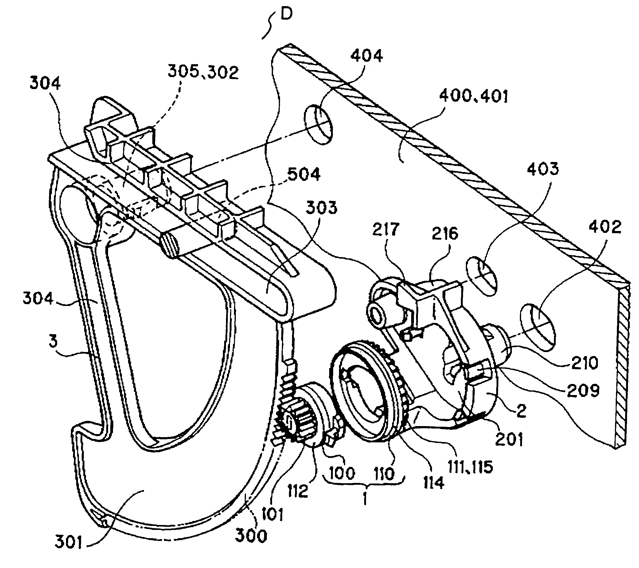
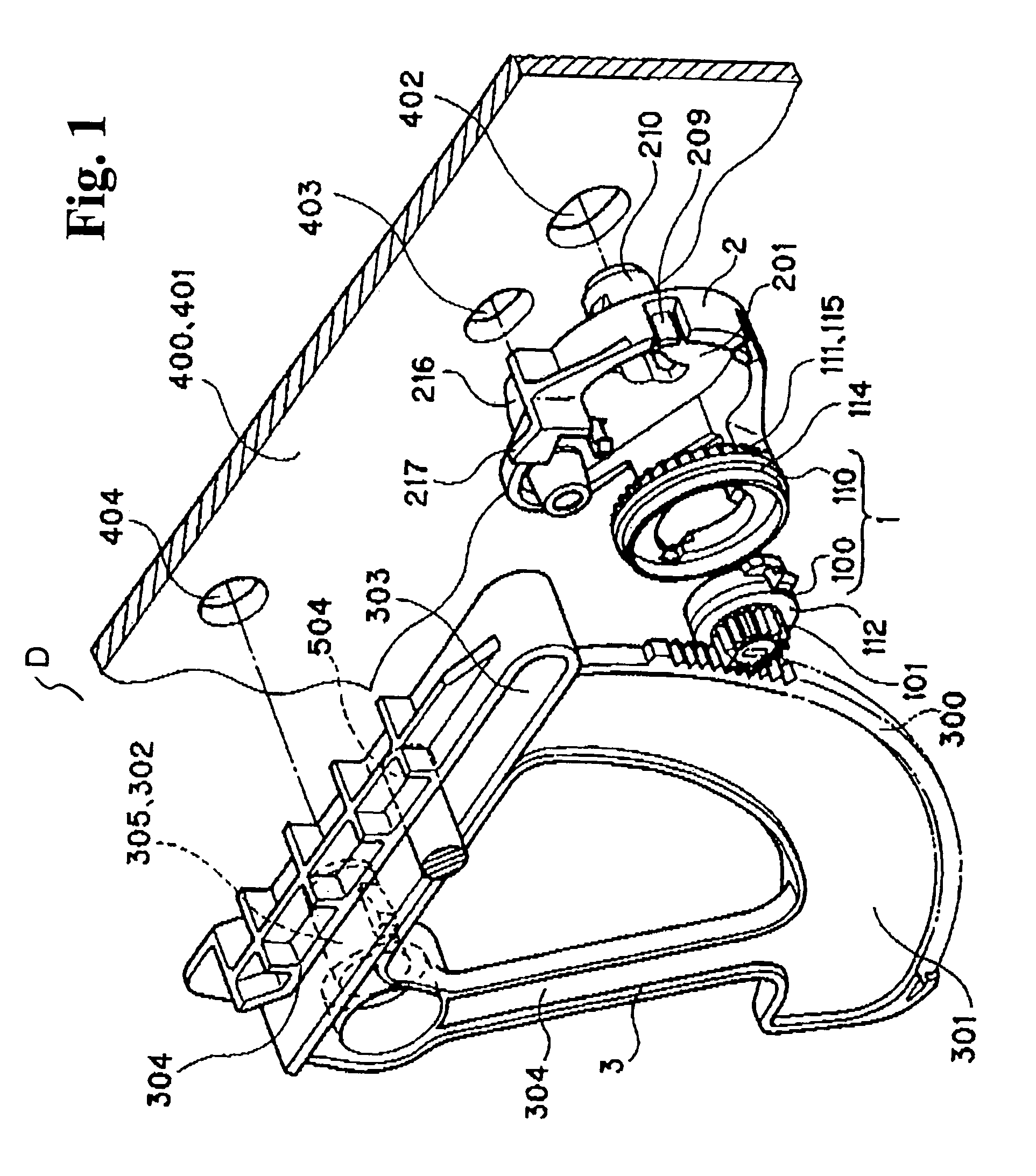
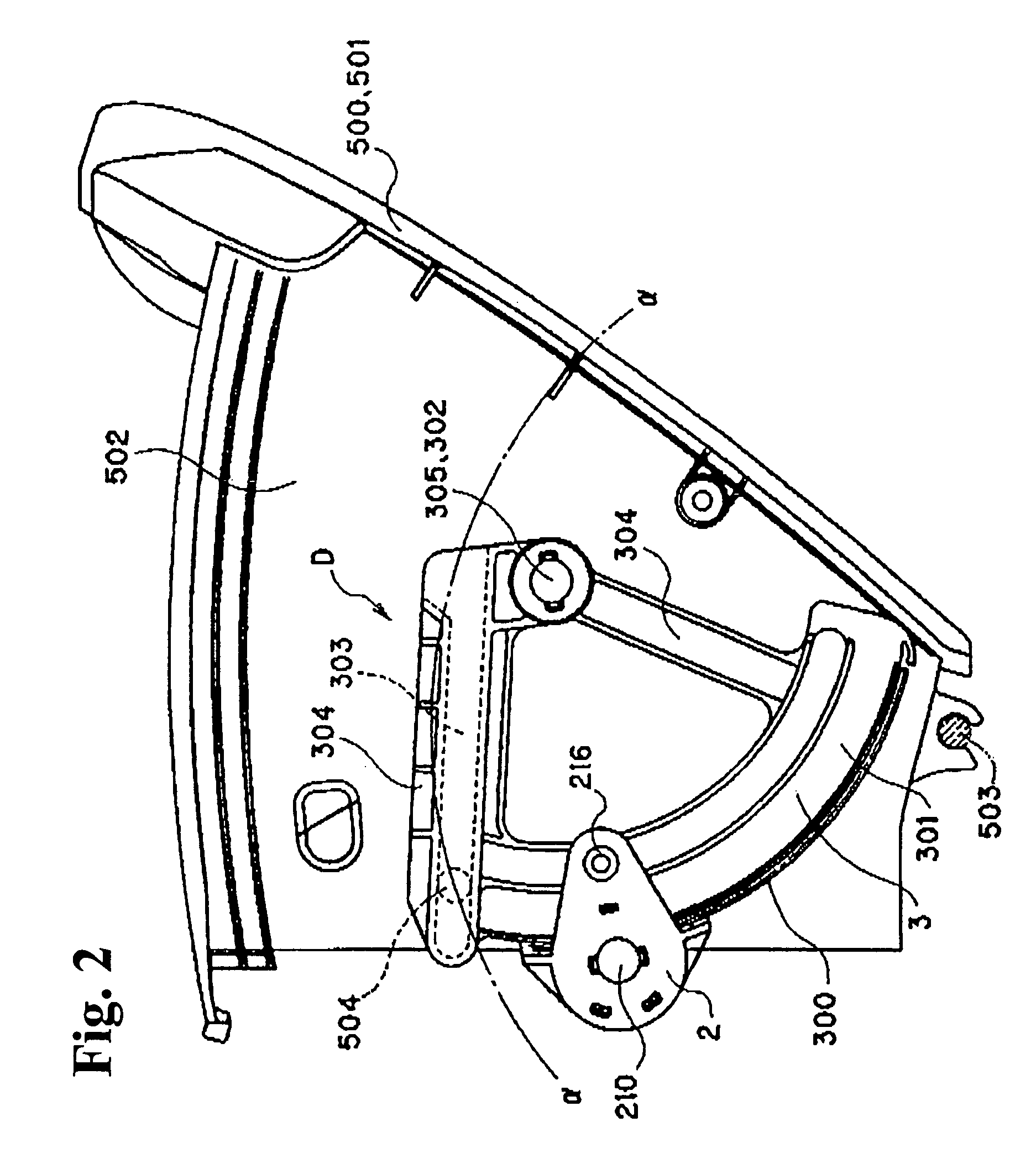
[0069]FIG. 1 is an exploded view of various components constituting a damper device D according to an embodiment. FIG. 2 through FIG. 4 show examples in which the damper device D damps a movement of a glove box 501 viewed from a side of the glove box 501 in a state that a panel 401 disposed inside an instrument panel with the damper device D is omitted. FIG. 5 shows a state that damping force is generated when only a first part 100 of a damping part 1 constituting the damper device D is rotated. FIG. 6 shows a state that the damping force is not generated when the damping part 1 constituting the damper device D is rotated as a whole inside a clutch case 2. That is, FIG. 6 shows the clutch case 2 and the damping part 1 viewed from a side opposite to that in FIG. 2, i.e. from a side facing a side plate 502 of the glove box 501.

[0070]FIG. 7 shows the damper device D viewe...


PUM


Abstract

A damper device applies damping force to a movable body assembled on a fixed body. The damper device includes a damping part, a clutch case attached to one of the fixed body and the movable body in a state having received the damping part, and a rack part moving or relatively moving accompanying movement of the movable body. The damper device effectively operate the movable body.

Description

BACKGROUND OF THE INVENTION AND RELATED ART STATEMENT[0001]The present invention relates to a damper mechanism provided on an opening-and-closing member or the like, for example, a glove box of an automobile, for absorbing impact when the opening-and-closing member is opened and closed, and a damper device for damping a movement of a movable body attached to a fixed body so that the movable body is drawn out or opened up.[0002]In a conventional damper mechanism disclosed in, for example, Japanese Patent Publication (Kokai) No. 05-76894 as shown in FIG. 24(A), a piston 104′ is disposed in a cylinder 100′ and slides along an inner wall surface of the cylinder 100′ with an O-ring 102′ in between. An annular cap 106′ is provided on a front end of the cylinder 100′ and a guide surface 106A′ having a curved surface is formed on an inner surface side of the cap 106′. A first space part 108′ is provided between the cap 106′ and the piston 104′, and a compression spring 110′ is disposed in t...

Claims


Application Information

Patent Timeline
Patent Type & Authority Patents(United States)
IPC IPC(8): E05F3/04B60R7/06E05F5/06
CPCB60R7/06E05F5/02E05F5/06E05Y2201/21Y10T16/276E05Y2201/266E05Y2900/538Y10T16/2771Y10T16/541E05Y2201/254
Inventor OKABAYASHI, SYUNSUKEHAYASHI, KENARAKAWA, MASARU
Owner NIFCO INC
Why Eureka
Try Eureka