
Top flange stud to plate tie

a technology of flange studs and ties, which is applied in the direction of rod connections, girders, manufacturing tools, etc., can solve the problems of insufficient uplift resistance of toe nailing, insufficient indexing of metal connectors for both single and double plates with the same part of the connector, and inability to provide tension resistance in addition, so as to achieve easy use and installation, and resist greater uplift loads

Active Publication Date: 2006-06-27
SIMPSON STRONG TIE
View PDF33 Cites 49 Cited by
  • Summary
  • Abstract
  • Description
  • Claims
  • Application Information

AI Technical Summary

Benefits of technology

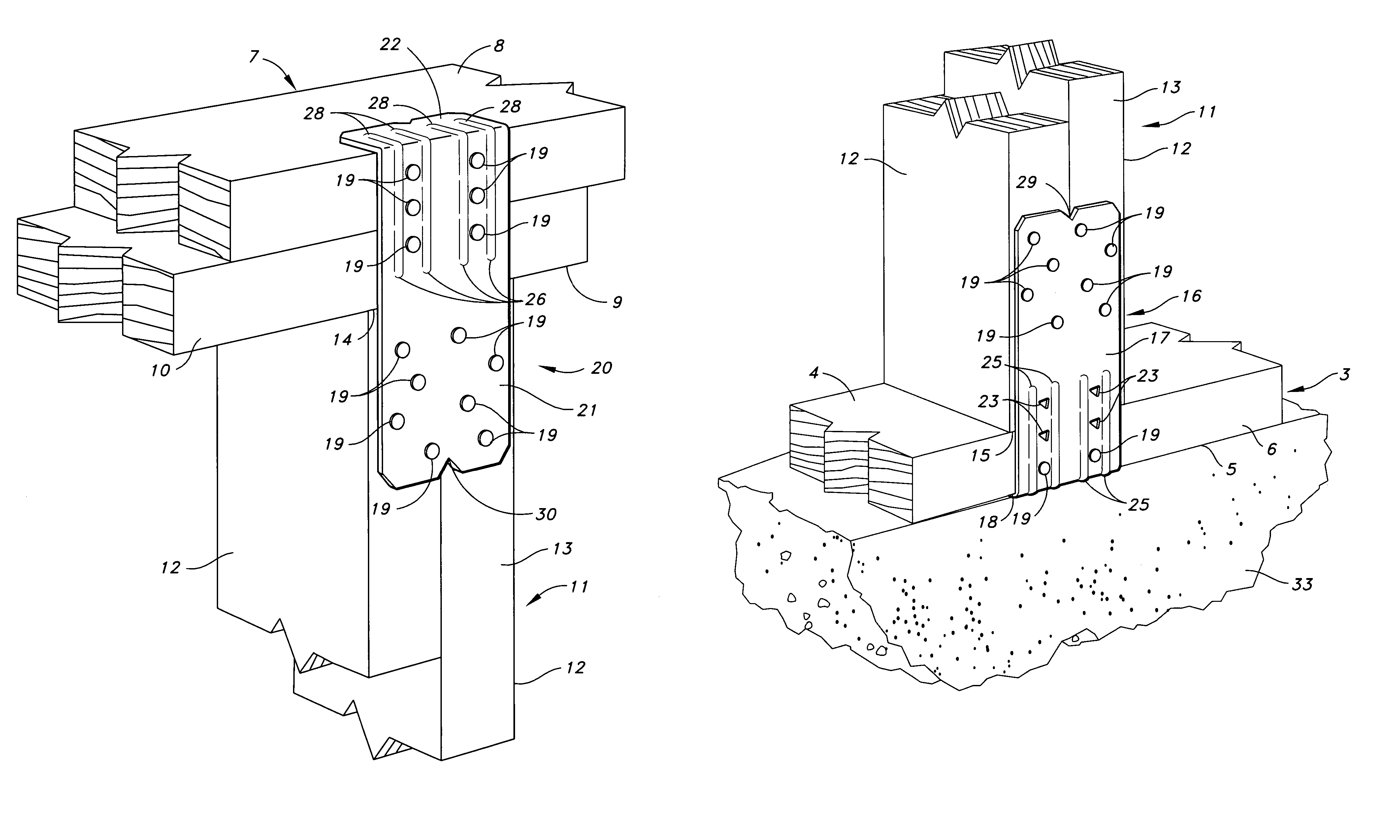
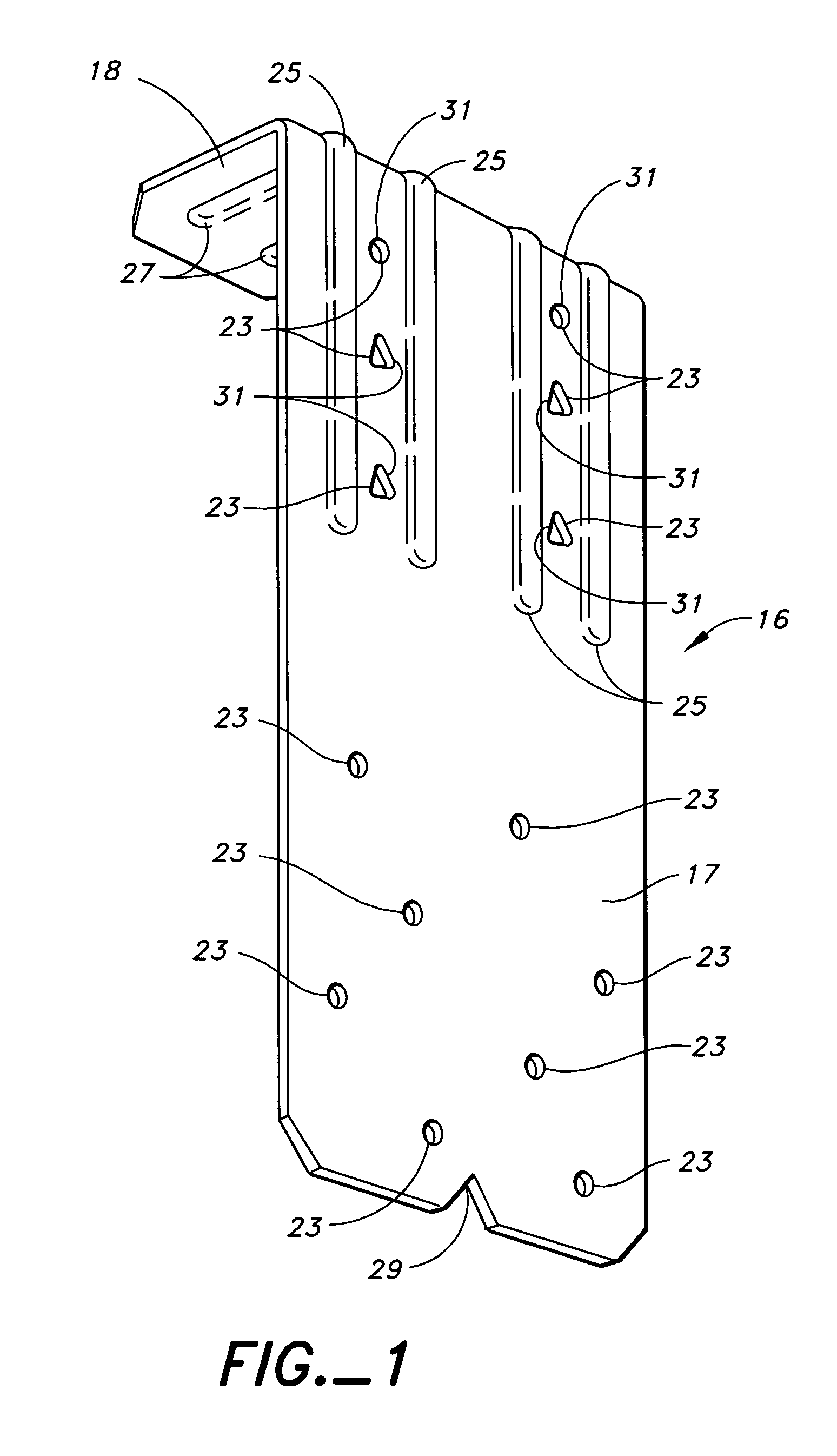
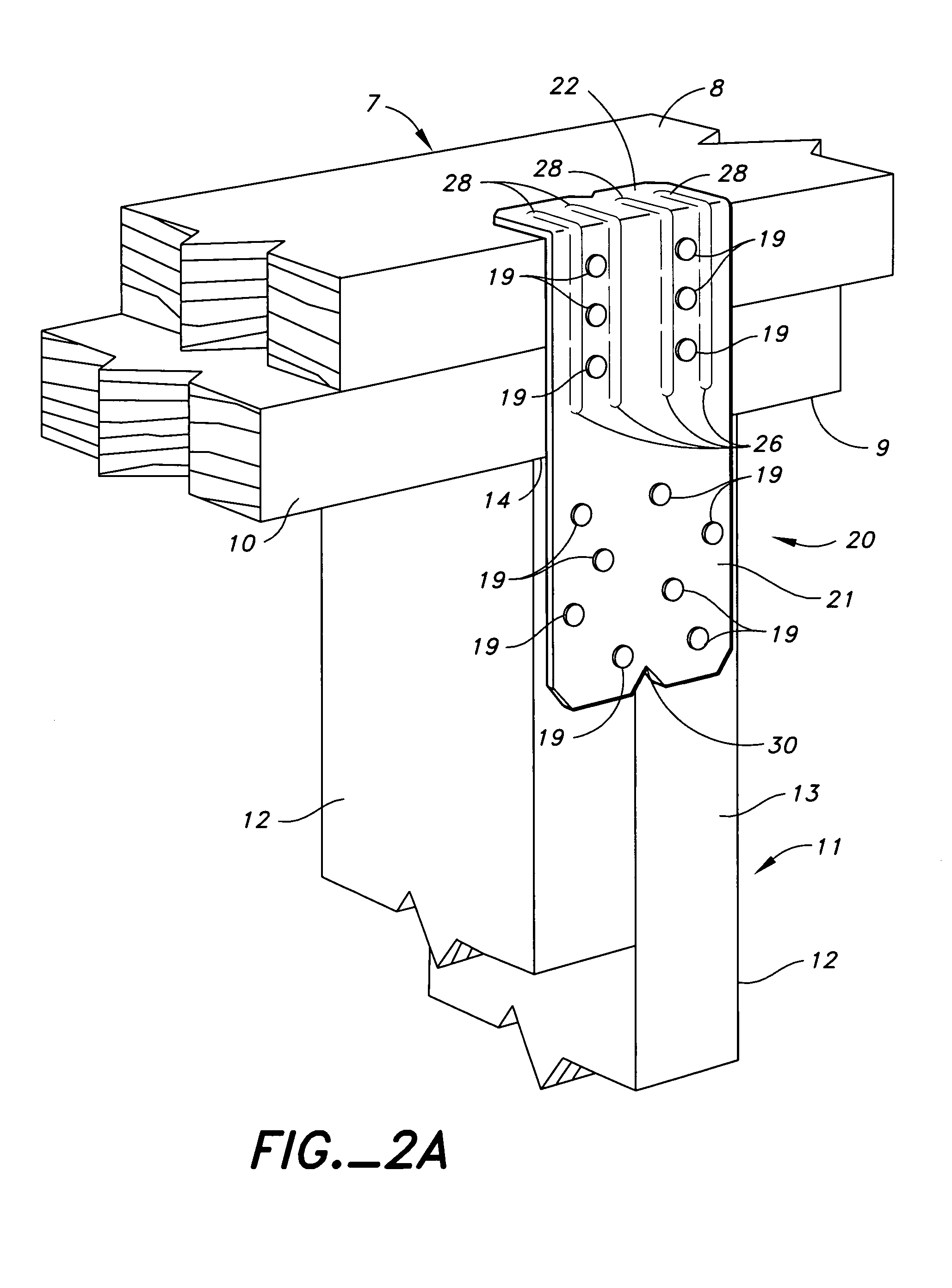
The present invention provides a sheet metal connector for connecting vertical studs to horizontal wood plates that is easier to use and can resist greater uplift loads. The connector is made up of identical connectors attached to the stud and plates of a building wall that resist tension loads through fasteners and a face member flange. The connector can be interchangeably used to connect the stud to either a top double wood plate or a bottom single wood plate. The connector allows for easy installation by allowing for full hammer strokes and quick installation with the best line of sight installation by providing that all nails are installed on the outside surface of the stud and plates. The connector also provides a better resistance to shear loads than pull-out loads.

Problems solved by technology

The problem with the toe nail stud to plate connection is the fact that end splitting of the stud is common; particularly if installation is effected by an unskilled workman but the main problem is that toe nailing creates inadequate resistance to uplift where the structure is subject to earthquake or high wind forces.
Some commercially available metal connectors have been placed on the market, which decrease wood splitting and improve uplift resistance, but these metal connectors do not provide indexing for both single and double plates with the same part of the connector.
Moreover, none provide tension resistance in addition to that provided by the fasteners with the same part used for indexing.

Method used


Image

  • Top flange stud to plate tie
  • Top flange stud to plate tie
  • Top flange stud to plate tie

Examples


Embodiment Construction

[0029]As best seen in FIG. 3, FIG. 12, FIG. 17 and FIG. 18, the present invention is a stud to plate tie connection 1 in a wood frame structure 2. The connection comprises a base plate 3, a top plate 7, an elongated stud 11, a first stud to plate tie connector 16, and a second stud to plate tie connector 20. The base plate 3, top plate 7 and elongated stud 11 are all typically nominal 2×4 wood members. Most typically, the base plate 3 is a single width, while the top plate 7 is typically a double width. The stud 11 is typically either a single 2×4 or a double 2×4, although triple ply or greater are also possible. These structural members could also be a material other than wood, such as steel. The base plate 3 has an upper face 4, a lower face 5, and an edge face 6. The top plate 7 has an upper face 8, a lower face 9, and an edge face 10. The elongated stud 11 has sides 12 and an edge face 13 therebetween and has an upper end 14 in abutting registration with the lower face 9 of the ...


PUM


Abstract

A connection in wood frame construction such as in frame walls of homes, wood framed apartment buildings and light wood framed commercial buildings. Specifically, the disclosure describes a pair of connectors for joining wall studs to a base plate and to a top plate for framing a wall. The two connectors used in the connection are identical and include an edge member for connection to the edge faces of the stud and the base or top plates, and a face member for engaging the lower face of the base plate or the upper face of the top plate. The face member is joined to the edge member and projects at a right angle thereto. The face member serves the dual purposes of locating the connected at the ends of the studs and of resisting tension forces.

Description

BACKGROUND OF THE INVENTION[0001]The most common connection in the construction of a residential or light frame commercial building is the connection of the vertical wall framing studs to the bottom and top horizontal wood plates. This connection is most commonly made by toe nailing at an angle through an end of the stud into the respective top or bottom wood plate.[0002]The problem with the toe nail stud to plate connection is the fact that end splitting of the stud is common; particularly if installation is effected by an unskilled workman but the main problem is that toe nailing creates inadequate resistance to uplift where the structure is subject to earthquake or high wind forces.[0003]Some commercially available metal connectors have been placed on the market, which decrease wood splitting and improve uplift resistance, but these metal connectors do not provide indexing for both single and double plates with the same part of the connector. Moreover, none provide tension resist...

Claims


Application Information

Patent Timeline
Patent Type & Authority Patents(United States)
IPC IPC(8): E04B1/00E04B1/26E04C3/12
CPCE04B1/2608E04C3/12Y10T403/4602
Inventor ROESSET, CHARLESSHAMROUKH, LOUAY A.
Owner SIMPSON STRONG TIE
Learn More