Supercharge control apparatus and supercharge control method for supercharged internal combustion engine

a control apparatus and internal combustion engine technology, applied in the direction of engine controllers, combustion engines, machines/engines, etc., can solve the problems of supercharger having a low supercharging capability, intake air flowing backward, surge,

Inactive Publication Date: 2006-06-27
TOYOTA IND CORP
View PDF19 Cites 17 Cited by
  • Summary
  • Abstract
  • Description
  • Claims
  • Application Information

AI Technical Summary

Benefits of technology

[0006]Accordingly, it is an objective of the present invention to raise the limitation of the flow rate of air supply in a case where the air fed from several supercharges are converged and supplied to cylinders.

Problems solved by technology

When the ratio of the pressure downstream-the compressor to the pressure upstream the compressor becomes excessively high in the turbocharger, surge occurs and intake air flows backward.
In a case where the air fed from several superchargers are converged and supplied to cylinders, if the supercharging capability of each supercharger differs from one another, the supercharger having a low supercharging capability (that is, the supercharger that supplies less amount of air to the cylinder) is likely to cause a surge.
Therefore, in a case where intake air fed from several superchargers are converged and supplied to the cylinders, there is a limitation in increasing the pressure ratio to increase the flow rate air supply to the cylinders due to the variation of the supercharging capability of the supercharges.

Method used


Image

  • Supercharge control apparatus and supercharge control method for supercharged internal combustion engine
  • Supercharge control apparatus and supercharge control method for supercharged internal combustion engine
  • Supercharge control apparatus and supercharge control method for supercharged internal combustion engine

Examples


first embodiment

[0020]the present invention will now be described with reference to FIGS. 1–3.

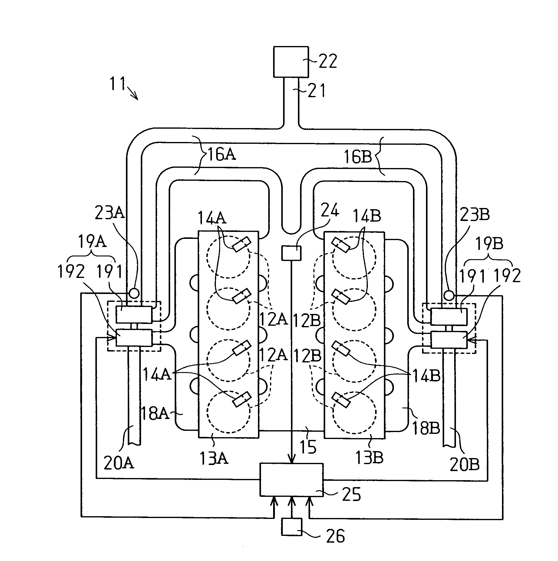
[0021]As shown in FIG. 1, an internal combustion engine 11 includes a first group of cylinders 12A and a second group of cylinders 12B. Fuel injection valves 14A are attached to a cylinder head 13A corresponding to the first group of cylinders 12A. Each fuel injection valve 14A corresponds to one of the cylinders 12A. Fuel injection valves 14B are attached to a cylinder head 13B corresponding to the second group of cylinders 12B. Each fuel injection valve 14B corresponds to one of the cylinders 12B. The fuel injection valves 14A, 14B inject fuel into the cylinders 12A, 12B.

[0022]The cylinder heads 13A, 13B are connected to an intake manifold 15. The intake manifold 15 is connected to branch intake passages 16A, 16B. A compressor unit 191 of a first supercharger 19A is located in the branch intake passage 16A and a compressor unit 191 of a second supercharger 19B is located in the branch intake passage 16B....

second embodiment

[0047]A control computer 25C controls the opening degree of the vane in the turbine 192 of each supercharger 19A, 19B in accordance with the surge prevention control program shown in the flowchart of FIG. 4(b).

[0048]The surge prevention control program of the second embodiment differs from the first embodiment in that steps S6, S8 of the surge prevention control program according to the first embodiment are replaced with steps S9, S10. The steps S9, S10 will be described below.

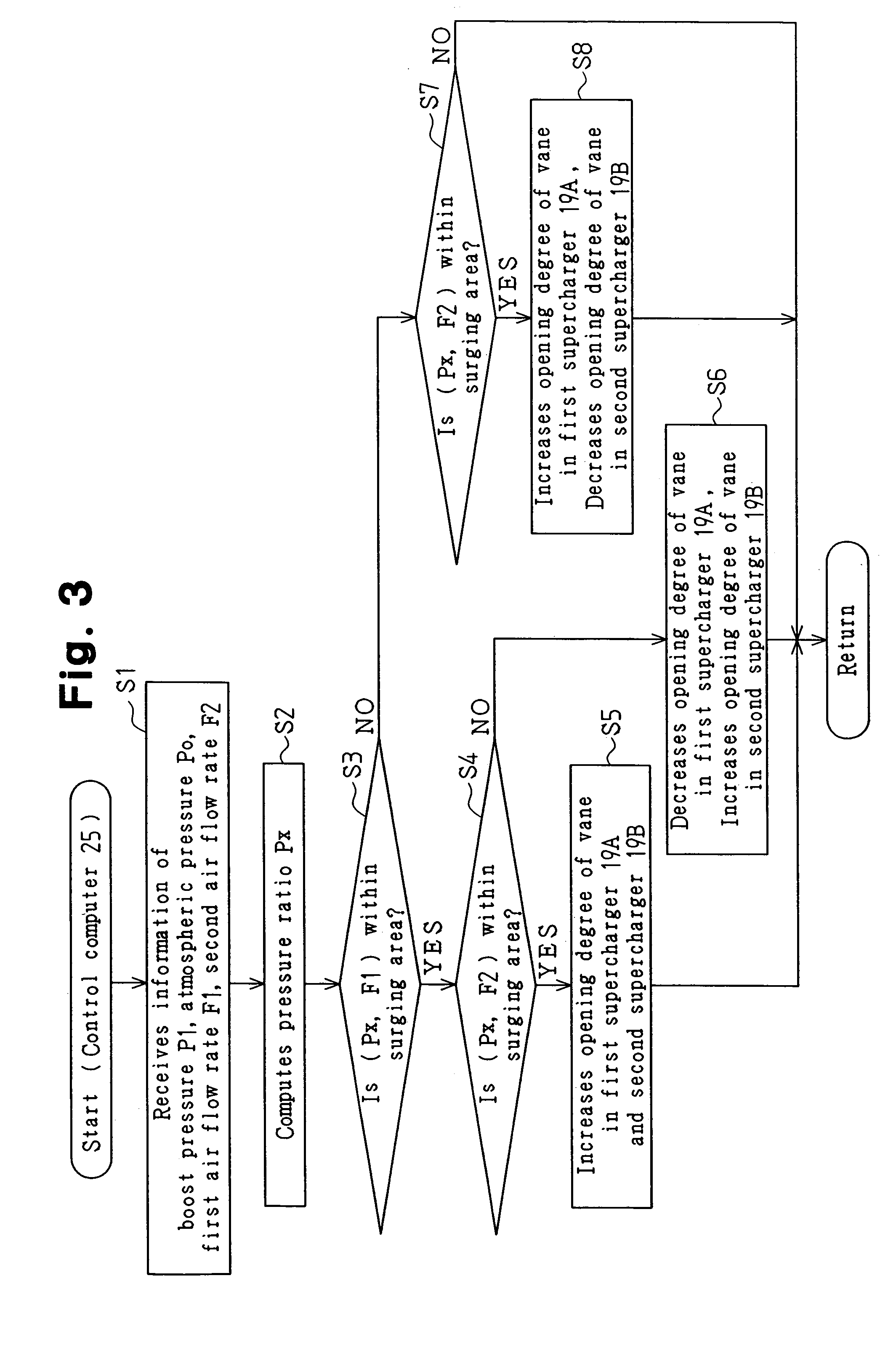
[0049]If the decision outcome of step S4 is NO, that is, if it is determined that the boost condition (Px, F1) is within the surging area E and the boost condition (Px, F2) is not within the surging area E, the control computer 25C proceeds to step S9 and decreases the opening degree of the vane in the first supercharger 19A. Decreasing the opening degree of the vane in the first supercharger 19A increases the air flow rate of the first supercharger 19A. Increasing the air flow rate of the first supercharger ...

third embodiment

[0056]the present invention will now be described with reference to FIGS. 5(a) and 5(b). Same reference numerals are used for those components, which are the same as the corresponding components of the first embodiment.

[0057]A control computer 25D according to the third embodiment controls the opening degree of the vane in the turbine 192 of each supercharger 19A, 19B in accordance with the surge prevention control program shown in the flowchart of FIG. 5(b).

[0058]The surge prevention control program of the third embodiment differs from that of the first embodiment in that steps S6, S8 of the surge prevention control program according to the first embodiment are replaced with steps S1, S12. The steps S11, S12 will be described below.

[0059]If the decision outcome of step S4 is NO, that is, if it is determined that the boost condition (Px, F1) is within the surging area E and the boost condition (Px, F2) is not within the surging area E, the control computer 25D proceeds to step S11 a...


PUM


Abstract

A detecting device detects boost condition of each of a plurality of superchargers. The detecting device includes at least two of a pressure ratio detecting unit, which detects the ratio of the pressure downstream each supercharger to the pressure upstream each supercharger; an air flow rate detecting unit, which detects the flow rate of air passing through each supercharger; and a rotational speed detecting unit, which detects the rotational speed of each supercharger. When it is determined that the boost condition of only part of the superchargers is within the surging area, a control unit increases the air flow rate of the supercharger, the boost condition of which is determined to be in the surging area. Therefore, the limitation of the flow rate of air supply is raised.

Description

BACKGROUND OF THE INVENTION[0001]The present invention relates to a supercharge control apparatus and a supercharge control method for a supercharged internal combustion engine that converges intake air fed from superchargers and supplies the intake air to cylinders.[0002]A supercharger for improving the intake efficiency of an internal combustion engine includes an exhaust-gas driven turbocharger, which supercharges cylinders by an energy of exhaust-gas (for example, Japanese Laid-Open Patent Publication No. 2001-342840, Japanese Laid-Open Patent Publication No. H02-305322). The turbocharger includes a variable displacement turbocharger that adjusts the flow velocity of exhaust gas by selectively opening and closing a vane in a turbine. Adjusting the flow velocity of exhaust gas controls the boost pressure.[0003]When the ratio of the pressure downstream-the compressor to the pressure upstream the compressor becomes excessively high in the turbocharger, surge occurs and intake air f...

Claims


Application Information

Patent Timeline
Patent Type & Authority Patents(United States)
IPC IPC(8): F02B33/44F02B37/00F02B37/12F02B37/24F02D23/00F02B39/16F02B37/007F02B37/22
CPCF02B37/007F02B37/24F02B39/16F02B37/22F01N13/107Y02T10/144Y02T10/12
Inventor TAKAHASHI, YOSHIYUKINARITA, YUJISUZUKI, HISANOBU
Owner TOYOTA IND CORP
Why Eureka
Try Eureka