Piston-cylinder unit

a piston-cylinder unit and piston-cylinder technology, applied in the direction of vibration dampers, wing fasteners, mechanical instruments, etc., can solve the problems of large overall length and high outlay on piston-cylinder units

Inactive Publication Date: 2006-06-27
STABILUS
View PDF18 Cites 26 Cited by
  • Summary
  • Abstract
  • Description
  • Claims
  • Application Information

AI Technical Summary

Benefits of technology

[0007]Since the cylinder can now be of shortened design and also the piston has at most only to be extended slightly, a very compact piston-cylinder unit is achieved. The integration of the volume-equalizing chamber in the piston furthermore results in a reduction in the components which are required and therefore also in a considerable reduction of costs for the piston-cylinder unit.
[0016]For reliable guidance of the closing elements, the first and / or the second valve, which can be opened under high pressure, can have a valve chamber which is formed in the piston and in which a valve piston is guided displaceably in a sealed manner. The valve piston bears a closing element which is acted upon in the closing direction by a force and is acted upon in the opening direction by the pressure of one of the working spaces, and by means of which the valve passage of the first and / or second valve, which can be opened under high pressure, can be blocked.
[0019]Another possibility is for the closing element or the valve piston to be acted upon in the closing direction by a force from one or more spring arms which are supported on the piston and the force of which is degressive on the path of movement of the closing element or the valve piston in the opening position, at least in the last part of the path of movement, and is at least largely zero in the opening position. This has the advantage that, during displacement of the piston, the closing element or the valve piston remains in its open position, and, in particular if the piston moves slowly, a fluttering movement of the closing element does not occur.
[0021]This is achieved in a simple manner in that a permanent magnet is arranged on the valve piston or the piston, and a ferromagnetic component is arranged on the piston or valve piston opposite the permanent magnet in the direction of movement of the valve piston.

Problems solved by technology

This design results in a large overall length and a high outlay on components for the piston-cylinder unit.

Method used


Image

  • Piston-cylinder unit
  • Piston-cylinder unit
  • Piston-cylinder unit

Examples


Embodiment Construction

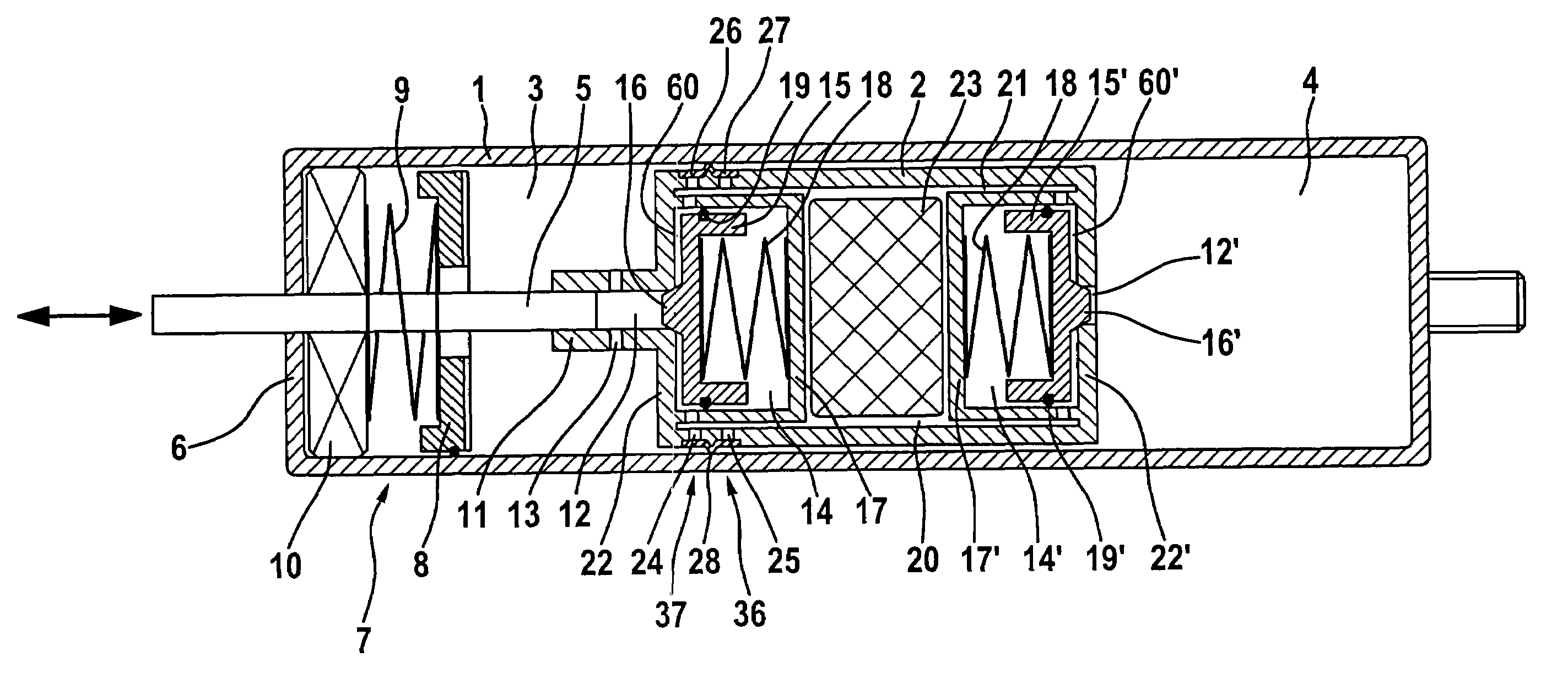
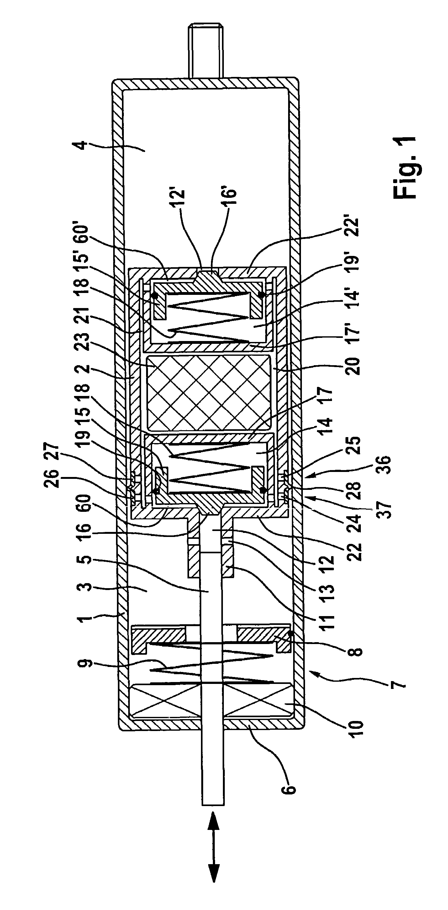
[0063]The piston-cylinder units illustrated in the figures are door arresters, which act in an infinitely variable manner, for motor vehicles. They have a closed cylinder 1 in which a piston 2 is guided in a displaceable manner, the piston dividing the interior of the cylinder 1 into a working space 3 near the piston rod and a working space 4 away from the piston rod. The two working spaces 3 and 4 are filled with oil.

[0064]A piston rod 5 is arranged on one side of the piston 2 and extends through the working space 3, and is guided in a sealed manner to the outside through a seal 10 and through an end closing wall 6 of the cylinder 1.

[0065]Arranged adjacent to the closing wall 6 in the working space 3 is an end position damping means 7 comprising a damping piston 8, which can be freely displaced axially in the working space 3, and a compression spring 9, which is arranged between the damping piston 8 and the closing wall 6.

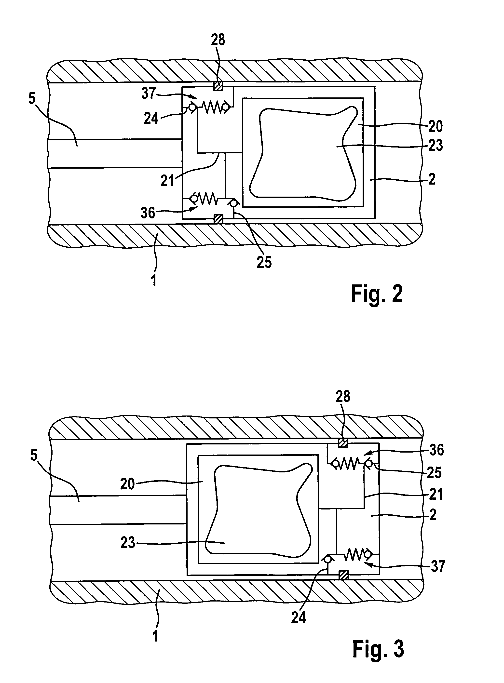
[0066]In order to fasten the piston rod 5 to the piston 2, t...


PUM


Abstract

A piston is guided in an axially displaceable manner sealed off from a closed cylinder via an annular seal radially surrounding it, and divides the cylinder interior into a working space near the piston rod and a working space away from the piston rod. The two working spaces are filled with a hydraulic fluid. The piston has a one-sided piston rod which extends through the working space near the piston rod and is guided in a sealed manner to the outside through an end closing wall of the cylinder. A first valve can be opened under high pressure to connect the working space away from the piston rod to the working space near the piston rod. A second valve can be opened under high pressure to connect the working space near the piston rod to the working space away from the piston rod. A volume-equalizing chamber for receiving the amount displaced from the working space away from the piston rod, which is greater than the amount displaced from the working space near the piston rod. The volume-equalizing chamber is arranged in the piston, and the working space away from the piston rod can be connected to the volume-equalizing chamber via the first valve and the working space near the piston rod can be connected to it via the second valve. The volume-equalizing chamber can be connected to the working space away from the piston rod via a first nonreturn valve and can be connected to the working space near the piston rod via a second nonreturn valve.

Description

BACKGROUND OF THE INVENTION[0001]1. Field of the Invention[0002]The invention is concerned with a piston-cylinder unit, having a closed cylinder in which a piston is guided in an axially displaceable manner sealed off from the cylinder via an annular seal radially surrounding it, and divides the cylinder interior into a working space near the piston rod and a working space away from the piston rod, the two working spaces being filled with a fluid, in particular with a hydraulic fluid. A one-sided piston rod extends through the working space near the piston rod and is guided in a sealed manner to the outside through an end closing wall of the cylinder. A first valve can be opened under pressure, in particular under high pressure, to connect the working space away from the piston rod to the working space near the piston rod. A second valve can be opened under high pressure to connect the working space near the piston rod to the working space away from the piston rod. A volume-equalizi...

Claims


Application Information

Patent Timeline
Patent Type & Authority Patents(United States)
IPC IPC(8): F16F9/04F16F9/34E05C17/30F15B15/20F16F9/06F16F9/32F16F9/46F16F9/50
CPCE05C17/305F16F9/464F16F9/064F16F2222/06F16F9/3214F15B15/20
Inventor MINTGEN, ROLFSCHWAB, WILHELMMUDERS, PAULBORN, FRANKSTEIN, ANDRE
Owner STABILUS
Why Eureka
Try Eureka