

Thrust bearing
a thrust bearing and bearing technology, applied in the direction of shafts and bearings, rotary bearings, rolling contact bearings, etc., can solve the problems of increased heat treatment cost and long manufacturing period, and achieve the effect of preventing the roller from coming out, preventing local wear of the roller, and eliminating excess material accumulation
Inactive Publication Date: 2006-06-27
NTN CORP
View PDF13 Cites 9 Cited by
- Summary
- Abstract
- Description
- Claims
- Application Information
AI Technical Summary
Benefits of technology
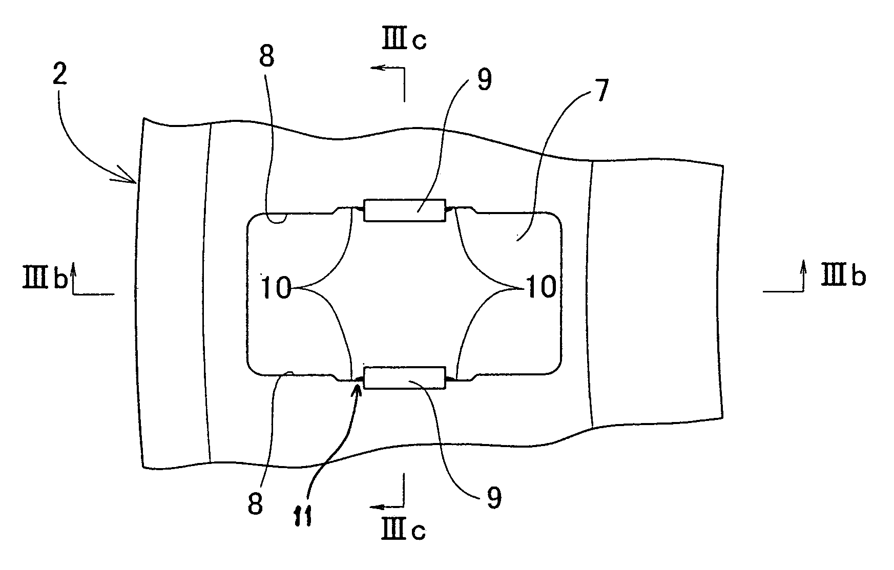
[0010]The retainer may be made of a thin steel plate, and the radial section of the pockets for housing the rollers may be formed in the shape of a W or an inverted V to make the retainer inexpensive.
[0011]If the retainer is formed with pockets having a radial section in the shape of an inverted V, substantially the radial center of roller guide surfaces on both sides of the inverted V-shaped pockets is compressed to form by plastic flow roller stopping claws protruding inwardly of the pockets from the respective roller guide surfaces. The roller stopping claws serve to prevent the rollers from coming out during assembly of the bearing. In particular, in a two-part type thrust bearing in which the pockets are open on one side, they are also effective in preventing the rollers from coming out during carburizing, hardening and tempering after assembling the bearing.
[0012]By forming recesses for receiving excess retainer material that plastically flows by compression on both sides of the portion of the roller guide surface where the roller stopping claw is to be formed, it is possible to prevent local wear of the rollers by eliminating build-up of excess material by plastic flow on the roller guide surfaces.
Problems solved by technology
With such a conventional integral type thrust bearing, since the bearing rings, retainer and rollers are individually heat-treated before assembling, heat treatment steps increase, so that the heat treatment cost increases.
Also, the manufacturing period tends to be long for adjustment of heat treatment steps for the respective parts.
Method used
View moreImage
Smart ImageViewing Examples

Examples
example
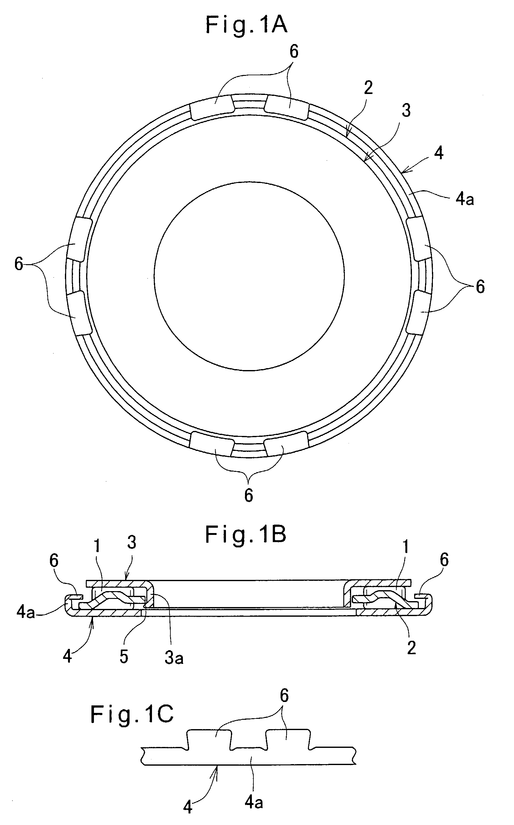
[0048]Thrust bearings were prepared which were of a three-part type bearing as shown in FIGS. 1A–1C and which were subjected to carburizing / hardening / tempering after assembling. As for the heat treatment conditions, they were carburized by keeping at 850° C. for 35 minutes in a carburizing atmosphere, oil-hardened and then subjected to tempering at 165° C. for 60 minutes. The rollers 1 were used which were oil-hardened at 840° C. for 30 minutes beforehand, and then subjected to tempering at 180° C. for 90 minutes. The bearing dimensions were as follows: inner diameter: 56 mm, outer diameter: 76 mm, and thickness: 4.8 mm.
Login to View More PUM
 Abstract
An integral type thrust bearing is proposed which can be manufactured with fewer heat treatment steps. The retainer and the inner and outer rollers not hardened are assembled together with rollers into a bearing and thereafter the assembled bearing is carburized, hardened and tempered. This eliminates the need for individual heat treatment of the retainer and the inner and outer rings and decreases heat treatment steps for the production of thrust bearings.
Description
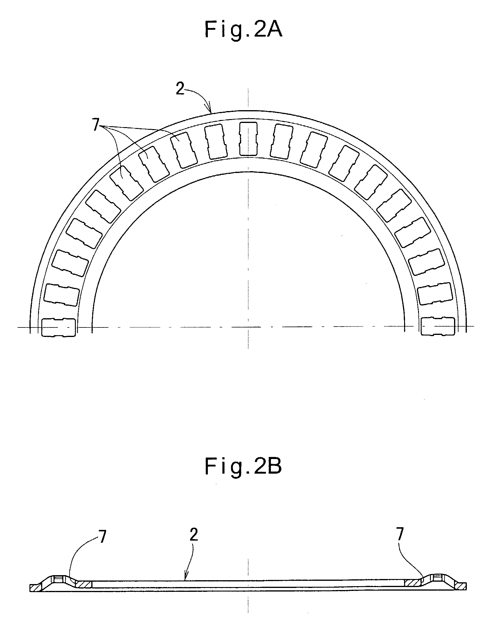
BACKGROUND OF THE INVENTION[0001]This invention relates to an integral type thrust bearing in which a bearing ring and a retainer for housing rollers are mounted inseparably.[0002]Among thrust bearings, there is an integral type in which the bearing rings and the retainer for housing the rollers are mounted inseparably from each other so that the thrust bearing can be easily mounted in a housing or on a shaft.[0003]FIGS. 10A and 10B show an example of such an integral type thrust bearing. It is a three-part type bearing having a retainer 2 for radially housing a plurality of rollers 1, an inner ring 3 having a flange 3a on the inner-diameter side, and an outer ring 4 having a flange 4a on the outer-diameter side. The inner and outer edges of the retainer 2 are engaged by outwardly protruding claws 5 and inwardly protruding claws 6 formed by staking at the tips of the flanges 3a and 4a, respectively, so that the inner and outer rings 3, 4 and the retainer 2 are inseparable from each ...
Claims
Login to View More Application Information
Patent Timeline
 Patent Type & AuthorityPatents(United States)
IPC IPC(8): F16C19/30F16C27/04F16C33/00F16C19/32F16C33/54F16C33/62F16C33/64F16C43/04
CPCF16C19/30F16C33/541F16C43/04F16C33/64F16C33/543
InventorFUJIOKA, NORIOYAMAMOTO, KAZUYUKI
OwnerNTN CORP