Dual chuck electrical hand drill

a dual-chuck, hand-held technology, applied in the direction of portable power-driven tools, drilling machines, manufacturing tools, etc., can solve the problems of user dropping the dual-ended bit, overall distance, time-consuming,

Inactive Publication Date: 2006-06-27
KUHN JAYME K
View PDF27 Cites 24 Cited by
  • Summary
  • Abstract
  • Description
  • Claims
  • Application Information

AI Technical Summary

Problems solved by technology

Under many circumstances, such as working from ladders, this can be very awkward.
Not only is this time consuming, but the user may drop the d

Method used


Image

  • Dual chuck electrical hand drill
  • Dual chuck electrical hand drill
  • Dual chuck electrical hand drill

Examples


Embodiment Construction

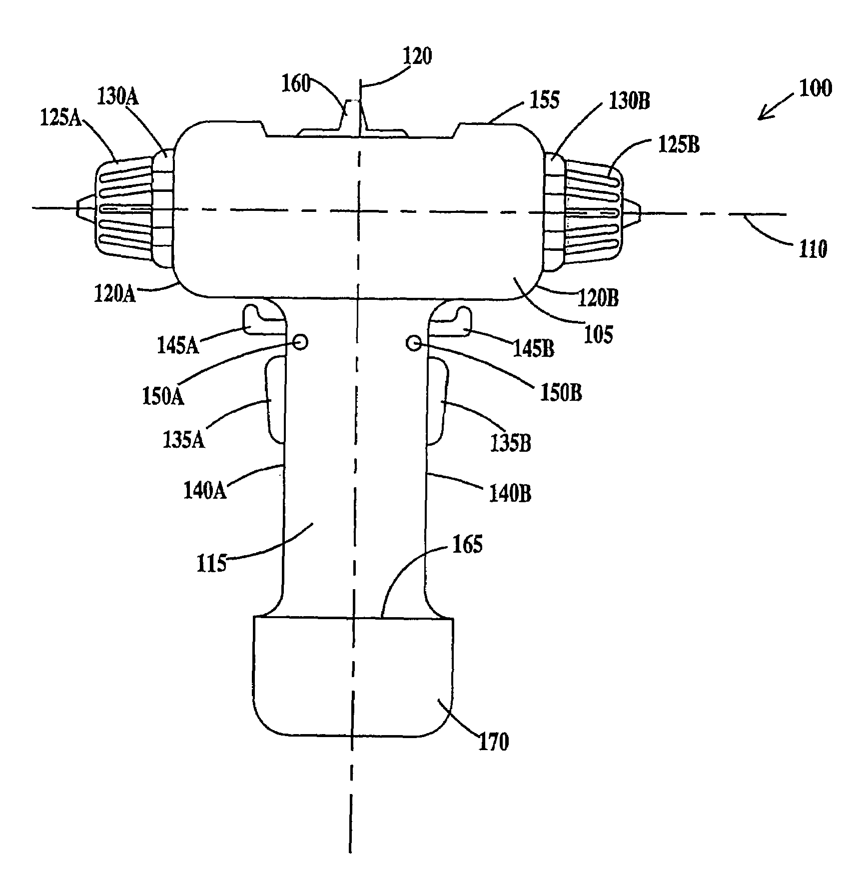
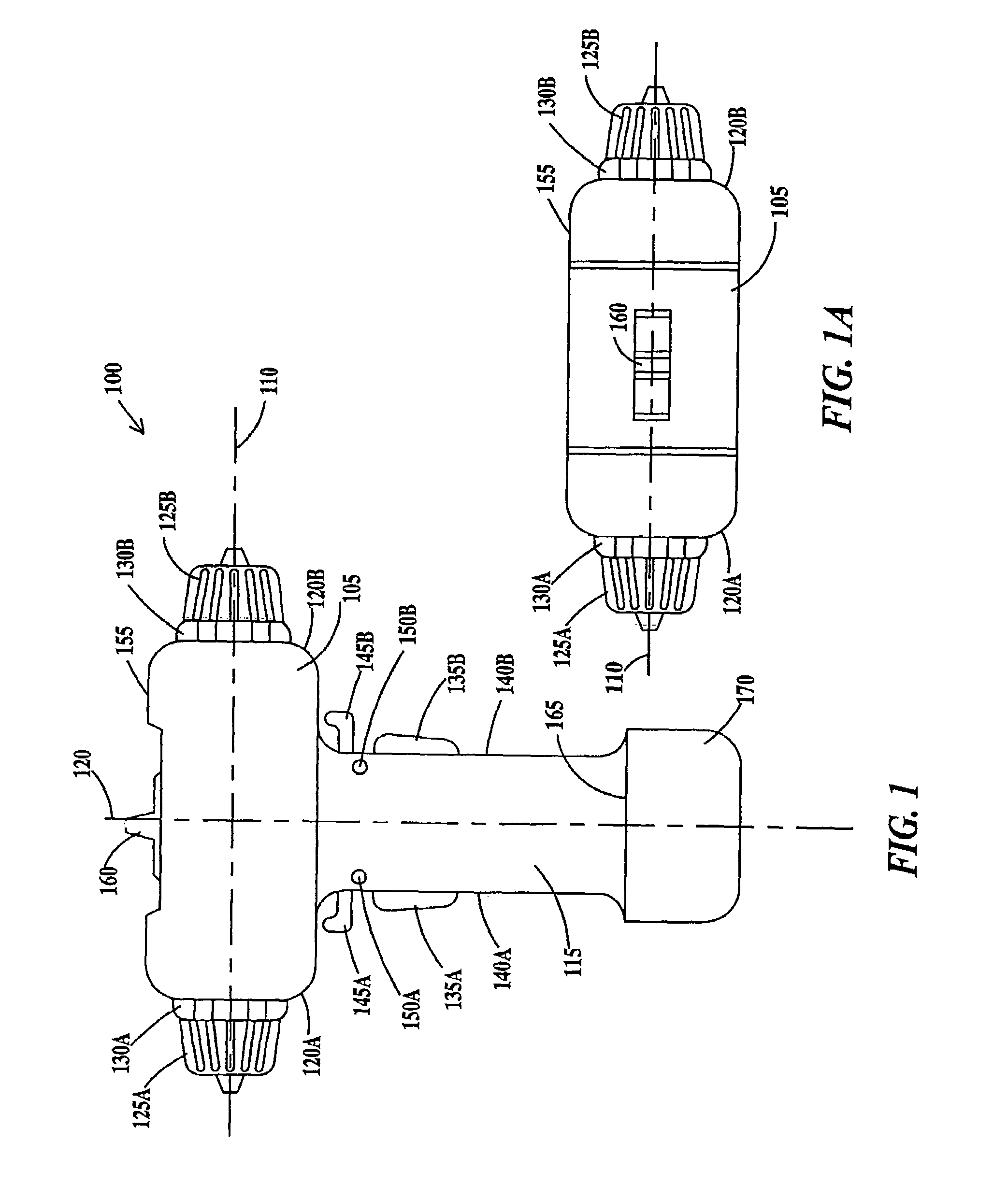
[0027]FIG. 1 a side view and FIG. 1A is a top view of a hand drill 100 according to the present invention. Hand drill 100 includes a power head 105 extending along a longitudinal axis 110 and a handle 115 extending along an axis 120 perpendicular to longitudinal axis 110. Longitudinal axis 110 defines the horizontal direction and axis 120 defines the vertical direction. Extending from opposite ends 120A and 120B of power head 105 are first and second chucks 125A and 125B. First and second chucks 125A and 125B include variable torque control rings 130A and 130B respectively.

[0028]Handle 115 includes first and second trigger switches 135A and 135B positioned on opposite sides 140A and 140B of handle 115. First and second trigger switches 135A and 135B are illustrated as spring loaded push switches but other types of switches, such as lever switches may be substituted. First trigger switch 135A controls the speed of rotation of first chuck 125A when the first chuck is selected or activ...


PUM

PropertyMeasurementUnit
Lengthaaaaaaaaaa
Poweraaaaaaaaaa
Electrical conductoraaaaaaaaaa

Abstract

A drill comprising: a power head having a first chuck positioned on a first end and a second chuck positioned on an opposite second end of the power head; a handle attached to the power head, the handle having a trigger switch for controlling a drive motor coupled to the first and second chucks.

Description

FIELD OF THE INVENTION[0001]The present invention relates to the field of electrical hand drills; more specifically, it relates to an electrically powered hand drill having two oppositely facing chucks.BACKGROUND OF THE INVENTION[0002]An ongoing need in the woodworking industry is to drill pilot holes before driving screws into materials. This has been traditionally accomplished by the use of two separate tools, namely a drill for drilling the pilot holes, and a screwdriver (which may be a hand tool, a powered tool, or another drill) for driving the screws. Use of two tools, requires repeatedly laying down the first tool and picking up the second tool. Under many circumstances, such as working from ladders, this can be very awkward. Recently, adapters have been developed that allow a double ended bit, for example a drill bit and a screw driver bit to be releasably held in an adapter held in the chuck. While this a eliminated the need for switching between two tools, there is still t...

Claims


Application Information

Patent Timeline
IPC IPC(8): B23B45/00B25F3/00B25F5/02
CPCB25F3/00B25F5/02Y10T408/37Y10T408/65Y10T408/38Y10T408/98
Inventor KUHN, JAYME K.
Owner KUHN JAYME K
Why Eureka
Try Eureka