Ceramic matrix composite airfoil trailing edge arrangement

a composite airfoil and composite material technology, applied in the direction of liquid fuel engines, marine propulsion, vessel construction, etc., can solve the problems of limiting the trailing edge design, turbine engines with operating temperatures that may exceed even the high temperature limits of known oxide and non-oxide ceramic materials, and leaving behind voids and/or cracks in the matrix-rich regions

Active Publication Date: 2006-06-27
SIEMENS ENERGY INC
View PDF25 Cites 67 Cited by
  • Summary
  • Abstract
  • Description
  • Claims
  • Application Information

AI Technical Summary

Problems solved by technology

However, thinness may result in weakness, and there are often structural limitations that limit the trailing edge design and necessitate the use of an aerodynamic design that is less than optimal.
However, modern gas turbine engines have operating temperatures that may exceed even the high temperature limits of known oxide and non-oxide ceramic materials.
Furthermore, the slurry-based matrix undergoes extensive volumetric shrinkage during drying and firing, which will leave behind voids and / or cracks in the matrix-rich regions.
Furthermore, the fibers in the trailing edge region 28 between inner and outer plies are relatively unconstrained, resulting in poor control of fibers, uneven distribution of porosity, and variable properties.

Method used


Image

  • Ceramic matrix composite airfoil trailing edge arrangement
  • Ceramic matrix composite airfoil trailing edge arrangement
  • Ceramic matrix composite airfoil trailing edge arrangement

Examples


Embodiment Construction

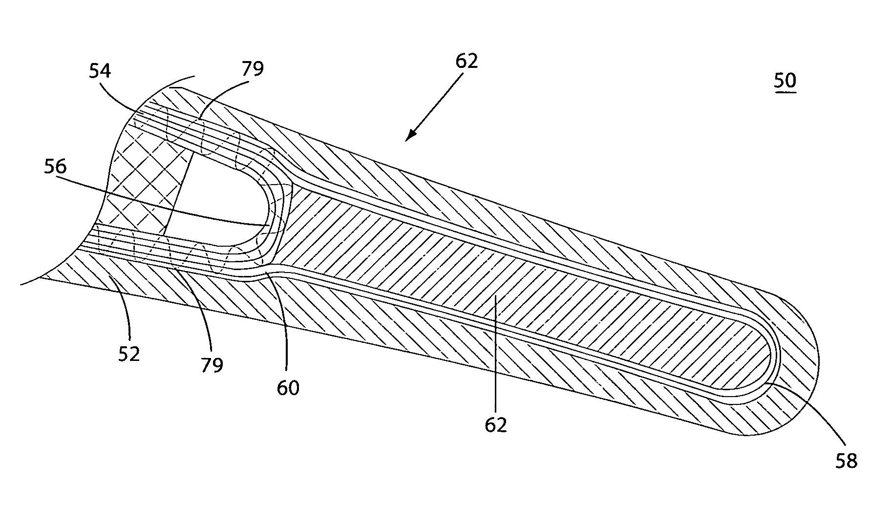
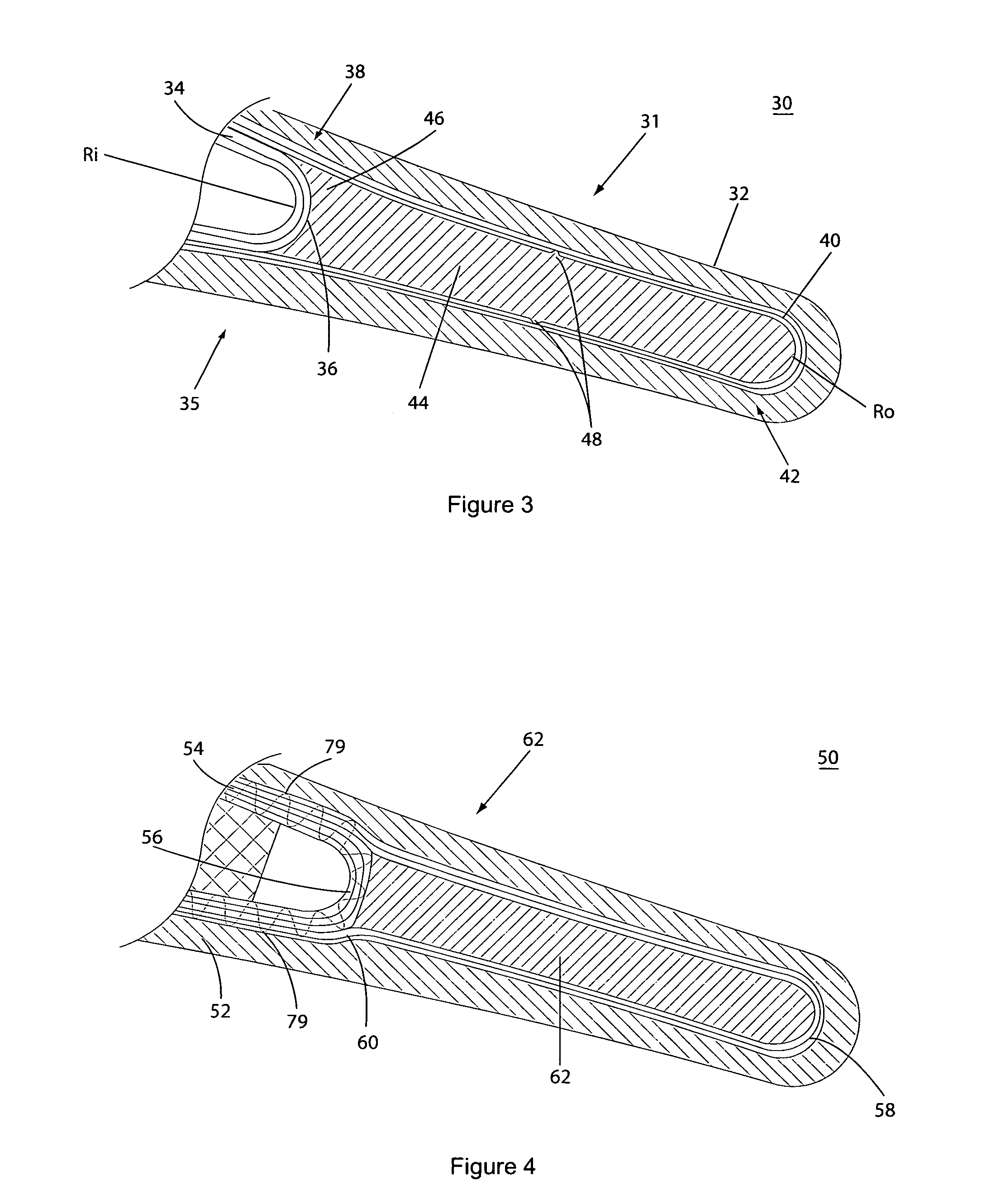
[0013]An improved CMC airfoil 30 as may be utilized in a gas turbine engine is illustrated in partial cross-section in FIG. 3. Support for an exterior insulating layer 32 that defines the airfoil shape is provided by a layer of ceramic matrix composite material 34 that extends continuously around the trailing edge portion 31 to support both the suction side 33 and the pressure side 35 of the airfoil 30. An inner wrap of plies 36 extends between the suction and pressure sides 33, 35 with a bend radius Ri to form an inner trailing edge portion 38. An outer wrap of plies 40 extends between the suction and pressure sides 33, 35 with a bend radius Ro to form an outer trailing edge portion 40. The inner and outer wraps 36, 38 together comprise the continuous layer of CMC material 34 along the suction and pressure sides 33, 35. Each of the inner wrap 36 and the outer wrap 38 are laid up to be sufficiently close-packed so that a process used to introduce matrix material (e.g. CVI or slurry ...


PUM

PropertyMeasurementUnit
bend radiusaaaaaaaaaa
pressureaaaaaaaaaa
coefficient of thermal conductivityaaaaaaaaaa

Abstract

An airfoil (30) having a continuous layer of ceramic matrix composite (CMC) material (34) extending from a suction side (33) to a pressure side (35) around a trailing edge portion (31). The CMC material includes an inner wrap (36) extending around an inner trailing edge portion (38) and an outer wrap (40) extending around an outer trailing edge portion (42). A filler material (44) is disposed between the inner and outer wraps to substantially eliminate voids in the trailing edge portion. The filler material may be pre-processed to an intermediate stage and used as a mandrel for forming the outer trailing edge portion, and then co-processed with the inner and outer wraps to a final form. The filler material may be pre-processed to include a desired mechanical feature such as a cooling passage (22) or a protrusion (48). The filler material may include an upper layer (77) and a lower layer (78) separated by an intermediate layer (76) that extends to between the inner wrap and the outer wrap along the suction and / or pressure sides.

Description

FIELD OF THE INVENTION[0001]This invention relates generally to ceramic matrix composite structures and more particularly to a ceramic matrix composite airfoil such as may be used in a gas turbine engine.BACKGROUND OF THE INVENTION[0002]The design of the trailing edge of an airfoil is preferably dictated by aerodynamic considerations. For improved aerodynamic performance, it is commonly preferred to provide a thin trailing edge for a gas turbine airfoil. However, thinness may result in weakness, and there are often structural limitations that limit the trailing edge design and necessitate the use of an aerodynamic design that is less than optimal.[0003]It is known to use ceramic matrix composite (CMC) materials for airfoils and other components of gas turbine engines. CMC materials advantageously provide higher temperature capability than metal and a high strength to weight ratio. However, modern gas turbine engines have operating temperatures that may exceed even the high temperatu...

Claims


Application Information

Patent Timeline
Patent Type & Authority Patents(United States)
IPC IPC(8): F03D3/02B63H1/26F01D5/18F01D5/28
CPCF01D5/187F01D5/282F01D5/284Y10T29/49341F05D2300/615Y10T29/49337F05D2300/603
Inventor MORRISON, JAY A.ALBRECHT, HARRY A.SHTEYMAN, YEVGENIYJACKSON, THOMAS BARRETT
Owner SIEMENS ENERGY INC
Why Eureka
Try Eureka