Cable modem module and transmitter-receiver

a technology of transmitter and receiver, which is applied in the direction of television system, coupling device connection, instruments, etc., can solve the problems of terminal breakage or deformation, and difficulty in completely suppressing unwanted radiation

Active Publication Date: 2006-06-27
HISENSE VISUAL TECH CO LTD
View PDF32 Cites 39 Cited by
  • Summary
  • Abstract
  • Description
  • Claims
  • Application Information

AI Technical Summary

Benefits of technology

[0003]The present invention relates to a cable modem module which permits unwanted radiation from a signal terminal mounted on a circuit board adapted to process a signal input thereto or output therefrom over a coaxial connector to be reduced, which may be superimposed on the input signal or output signal. The present invention also relates to a transmitter-receiver which has such a cable modem module built in.

Problems solved by technology

Even if the techniques disclosed in the afore-mentioned four Patent Publications are selectively combined to shield the circuit board, it-is difficult to completely suppress unwanted radiation.
In addition, for example, when a group of terminals protruding from the circuit board and the RF connector are oriented in different directions, trying to house the shield case which contains the RF connector and the circuit board in an outer case with little room may result in the terminals being broken or deformed.

Method used


Image

  • Cable modem module and transmitter-receiver
  • Cable modem module and transmitter-receiver
  • Cable modem module and transmitter-receiver

Examples


Embodiment Construction

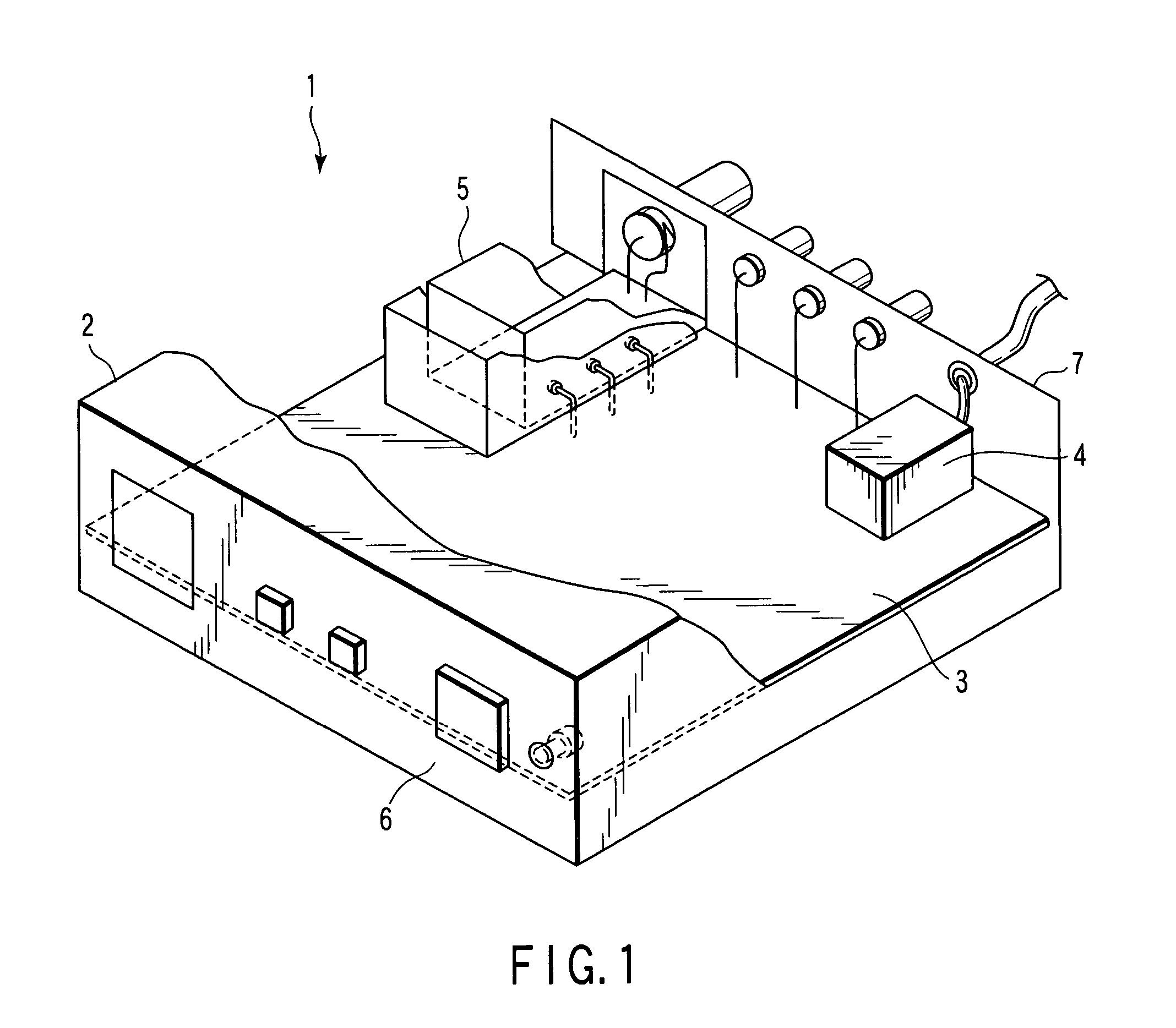
[0022]An embodiment of the present invention will be described hereinafter in detail with reference to the accompanying drawings. FIG. 1 shows a cable television (CATV) terminal device as a data communications terminal, indicated generally at 1, which is connected to a CATV network and allows a subscriber to receive video programs, music programs, or character data transmitted from a station and information entered by him or her to be transmitted to the program transmitting station.

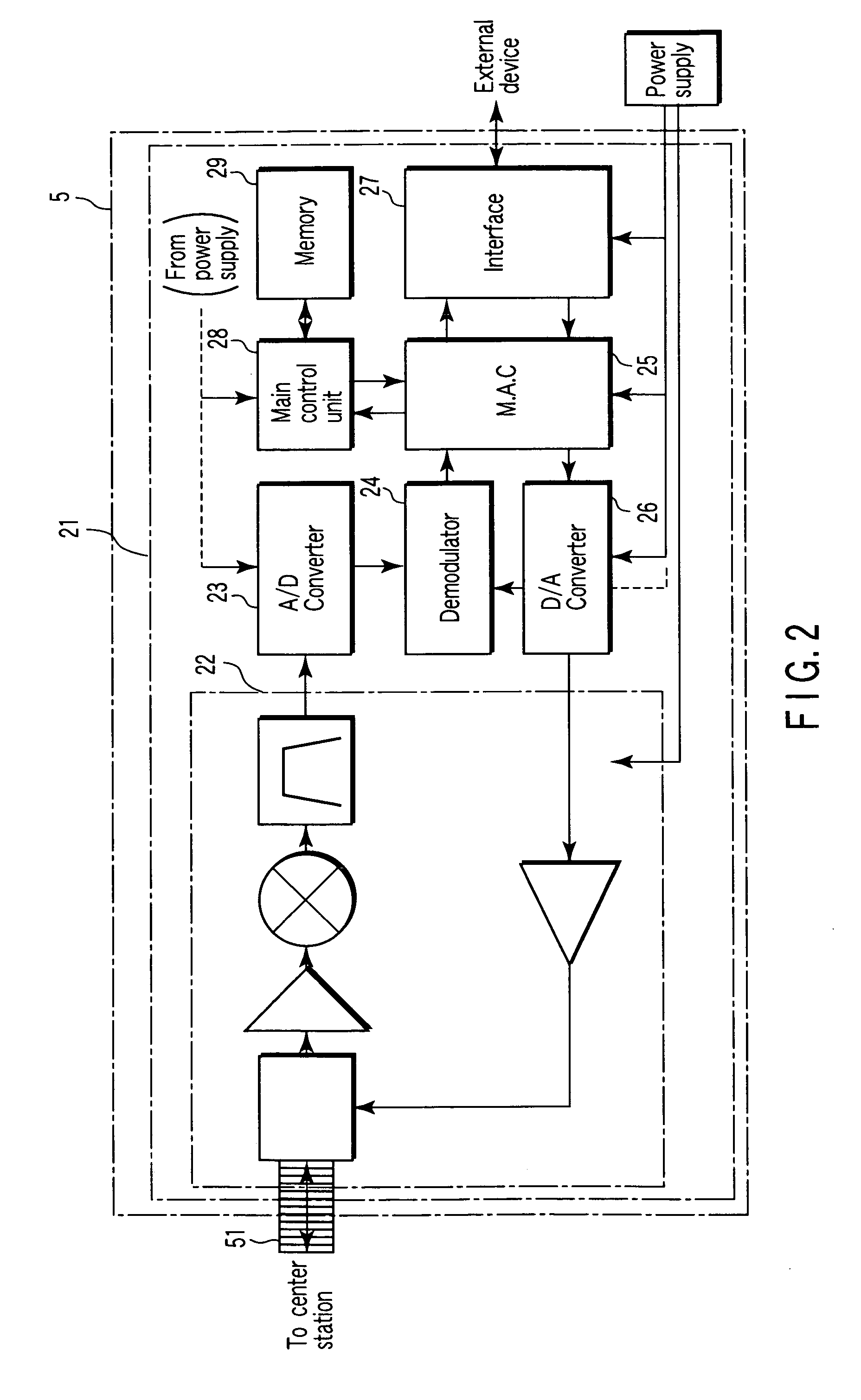
[0023]Video signals or character data are transmitted from the center station to each terminal (subscriber) via receive signals (down signals) of high frequencies of the order of, say, 90 to 860 MHz. On the other hand, information can be transmitted from each terminal to the center station via transmit signals of high frequencies of the order of, say, 5 to 65 MHz.

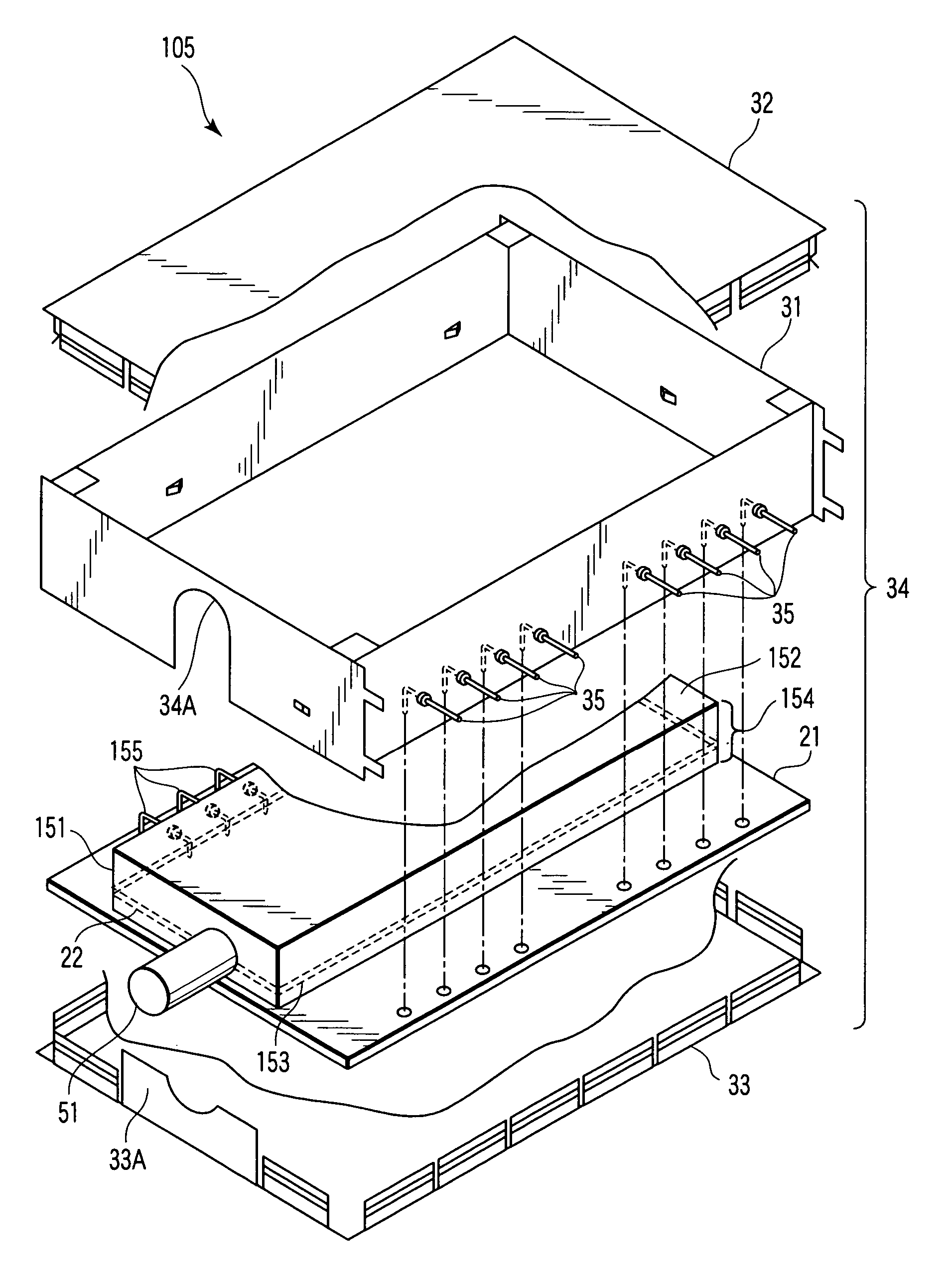
[0024]As shown in FIG. 1, the CATV terminal device 1 includes an outer case 2, a main circuit board 3, a power supply circuit board 4, a cable m...


PUM


Abstract

A cable modem module device includes a coaxial connector to transmit and receive high-frequency signals, a circuit board to which the coaxial connector is attached to protrude from its periphery in a direction parallel to its surface, and a first shield case formed in its portion corresponding to the coaxial connector with a cutout portion to avoid the coaxial connector so as to allow the circuit board to be housed from a direction perpendicular to the surface of the circuit board.

Description

CROSS-REFERENCE TO RELATED APPLICATIONS[0001]This application is based upon and claims the benefit of priority from prior Japanese Patent Application No. 2003-162022, filed Jun. 6, 2003, the entire contents of which are incorporated herein by reference.BACKGROUND OF THE INVENTION[0002]1. Field of the Invention[0003]The present invention relates to a cable modem module which permits unwanted radiation from a signal terminal mounted on a circuit board adapted to process a signal input thereto or output therefrom over a coaxial connector to be reduced, which may be superimposed on the input signal or output signal. The present invention also relates to a transmitter-receiver which has such a cable modem module built in.[0004]2. Description of the Related Art[0005]In a transmitter-receiver which receives a signal from outside or transmits a signal processed by an internal circuit to the outside over a radio-frequency (RF) cable (coaxial connector), the circuit board is housed in a shiel...

Claims


Application Information

Patent Timeline
Patent Type & Authority Patents(United States)
IPC IPC(8): H05K9/00G12B17/02H01R12/00H04B3/02H04N5/38
CPCH01R24/50H05K9/006H04L12/2898H04L12/2801H01R2103/00
Inventor ABE, SHUJIKUDO, KATSUYAISODA, TSUTOMUOOSAWA, MASAMIFUJIHARA, MIKINE
Owner HISENSE VISUAL TECH CO LTD
Why Eureka
Try Eureka