Compensation of simple fibre optic Faraday effect sensors

a technology of faraday effect and fibre optics, applied in the field of faraday optical current sensors, can solve the problems of b-field and current conversion factor, linear magnetic field interference from nearby inductors, and the calibration method compromises the conversion factor between b-field and current, so as to eliminate signal degradation

Active Publication Date: 2006-06-27
LANDIS & GYR OY
View PDF5 Cites 33 Cited by
  • Summary
  • Abstract
  • Description
  • Claims
  • Application Information

AI Technical Summary

Benefits of technology

[0012]The communication unit further provides the opportunity of performing a remote configuration of the system, giving an operator the possibility to configure the system, e.g. defining levels for peak currents, voltage drop out levels, time out values and alerting options.
[0035]The calibration may be performed to eliminate signal degradations, e.g. caused by worn or damaged components, and may also compensate for interference from other sources emitting electrical fields, such as other electrical cables.
[0036]When the sensor is placed on a specific electrical cable of a plurality of electrical conductive cables, the system may perform a calibration so as to eliminate the influence from the remaining part of the plurality of electrical conductive cables.

Problems solved by technology

This calibration method compromises for linear magnetic field interference from nearby inductors, and the conversion factor between the B-field and current.
It also compromises for production tolerances, conductor shape, conductor diameter and background noise, all when mounted in the active application.

Method used


Image

  • Compensation of simple fibre optic Faraday effect sensors
  • Compensation of simple fibre optic Faraday effect sensors
  • Compensation of simple fibre optic Faraday effect sensors

Examples


Embodiment Construction

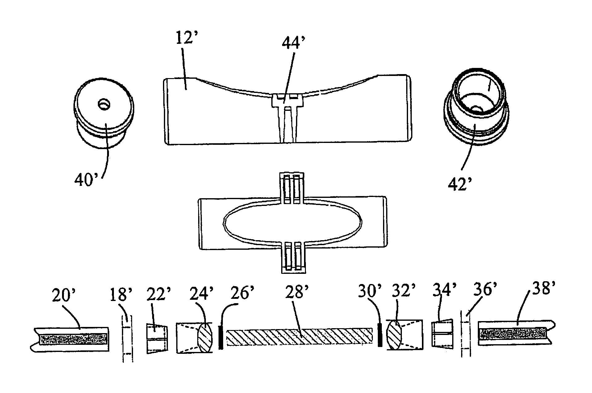
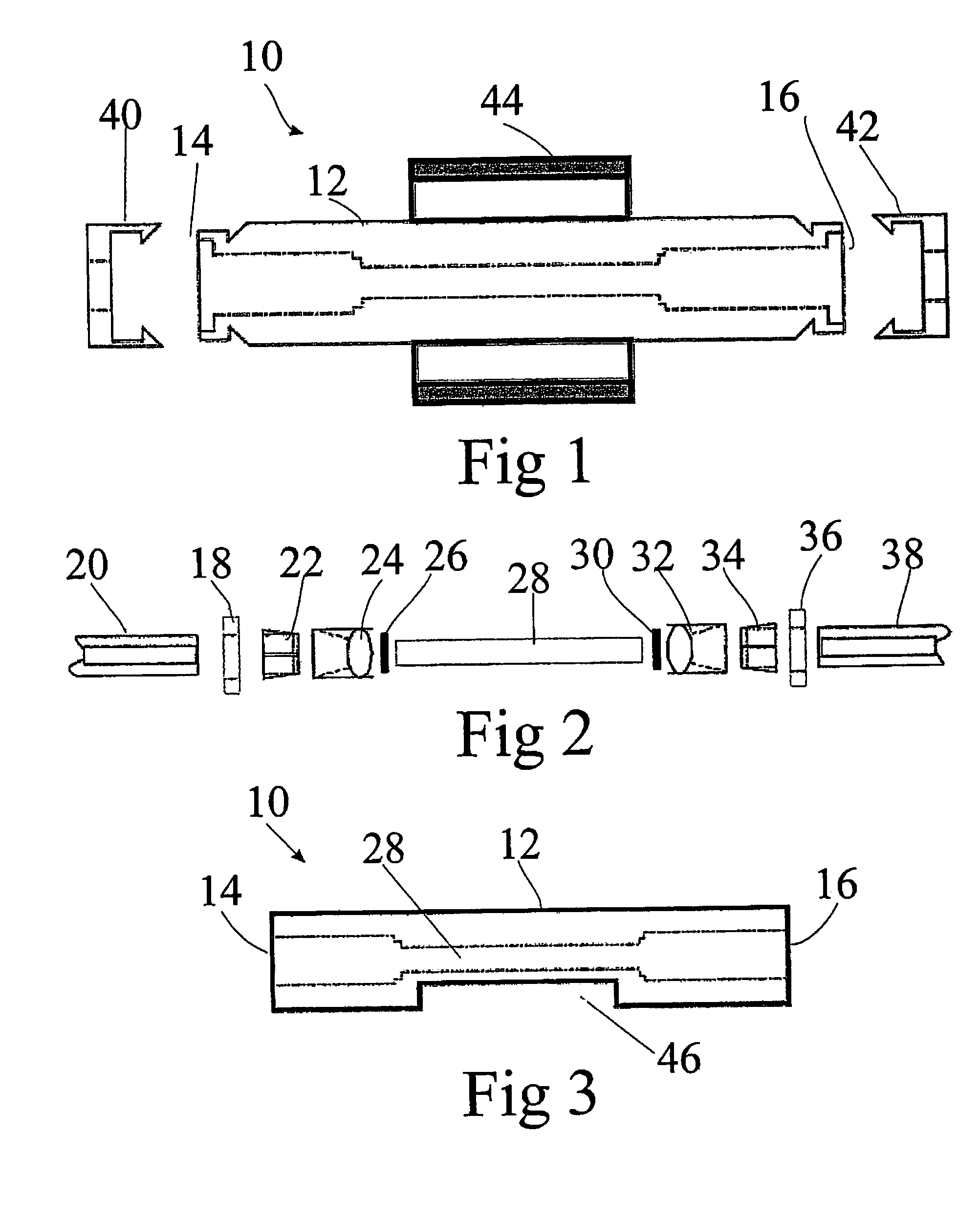
[0078]FIG. 1 is a schematic cross sectional view of a Faraday optical current sensor 10, and FIG. 2 is a zoomed schematic cross sectional view of the Faraday optical current sensor 10 of FIG. 1. The Faraday optical current sensor 10 comprises an oblong housing 12 defining a first and an opposite second end; designated 14 and 16 respectively. At the first end 14 of the housing 12 a first sealing 18 is mounted, the first sealing 18 having an aperture for receiving a first optical fibre 20. A first fibre fixture 22 mounted in the housing 12. The first fibre fixture 22 having a aperture for receiving an optical fibre 20. An optical lens 24 having a receiving section for receiving the optical fibre 20 and the fibre fixture 22. A first polarisation filter 26 mounted in optical continuation with the optical lens 24. A glass rod 28 in optical continuation with the first polarisation filter 26. At the opposite end of the glass rod 28 a second polarisation filter 30 is mounted in optical cont...


PUM


Abstract

An electric current measurement device includes a housing defining first and second open ends sealed by first and second sealing means, respectively; a first optical fibre received in an aperture in the first sealing means and in optical communication with a first optical lens in the housing; a first polarisation filter in the housing in optical communication with the first lens; a magneto-optical rod within the housing in optical communication with the first polarisation filter; a second polarisation filter in the housing in optical communication with the rod; and a second optical lens in the housing in optical communication with the second polarisation filter. The second sealing means has an aperture for receiving a second optical fibre fixed to the second lens. First and second lids, attachable to the first and second housing ends, respectively, include apertures for receiving the first and second optical fibres, respectively.

Description

CROSS-REFERENCE TO RELATED APPLICATIONS[0001]This application is a continuation of co-pending International Application No. PCT / DK2004 / 000337, filed May 12, 2004, and it claims the benefit, under 35 U.S.C. §119(e), of U.S. provisional application No. 60 / 471,551, filed May 19, 2003, the disclosure of which is incorporated by reference.FEDERALLY-SPONSORED RESEARCH OR DEVELOPMENT[0002]Not ApplicableBACKGROUND OF THE INVENTION[0003]The invention relates to a Faraday optical current sensor with polarimetric detection. The present invention further relates to a method of calibrating a current sensor system including a Faraday optical current sensor.[0004]The power industry has a need for monitoring transformer stations for power surges and measurement of large current pulses. For these purposes, a Faraday Effect current sensor has several advantages. A Faraday Effect current sensor may be constructed from dielectric materials, which is of grave importance when measuring at high currents i...

Claims


Application Information

Patent Timeline
Patent Type & Authority Patents(United States)
IPC IPC(8): G01R19/00G01R33/032G01R15/24G01R35/00
CPCG01R15/246G01R35/005
Inventor BJORN, LARS N.
Owner LANDIS & GYR OY
Why Eureka
Try Eureka