Proofing method, apparatus, and computer software product matching color and halftone screen properties

a technology of color and halftone screen and proofing method, applied in the direction of electrical equipment, electric digital data processing, instruments, etc., can solve the problems of low resolution, serious attempts to get proofs with the correct screens, and inaccurate representation of screening

Active Publication Date: 2006-06-27
BARCO GRAPHICS
View PDF16 Cites 39 Cited by
  • Summary
  • Abstract
  • Description
  • Claims
  • Application Information

AI Technical Summary

Benefits of technology

[0047]The method of the invention can be implemented fully digitally and need not require additional hardware or consumables. It is therefore an economical proofing solution for today's printing industry.
[0048]Compared to prior art methods, the embodiments of the present invention provide the following advantages:

Problems solved by technology

Note that these high quality ink-jet devices produce the grey levels per separation by using some inherent halftone (screening) methodology, but a user has no access to the screening, so that these devices are essentially grey-scale ink-jet devices.
The multiple grey levels per separation and per pixel enable these proofers to produce an acceptable level of detail rendition and contrast; otherwise, such a low resolution would be totally unacceptable, for example for offset or flexo platemaking.
Screening difference is also a problem with traditional prior-art film-based proofing, so that the screening and all related effects such as rosettes are accurately produced.
Other low-resolution devices do use screening, but such screening is unrelated to, and thus does not accurately represent the screening on the final print.
Thus, there have been serious attempts to get proofs with the correct screens.
Color management is not used since current color management tools drastically change the screened dot percentages of the different separations.
With the current state of the art, these screened proofers still have important drawbacks:Screened proofers are very expensive.
Typically, they are two to three times more expensive than the continuous tone ink-jet digital proofers.Making a proof is a time consuming operation.
It may take more than 30 minutes to make a single proof, and the process may require operator assistance.The proofing consumables are expensive for such screened proofers.Spot colors colorants are not widely available for such proofing processes.
In practice, this means that these screened proofers may be able to handle normal offset CMYK workflows well, but have serious trouble with more cumbersome printing processes such as flexography for packaging, which uses process ink CMYK colorants that deviate significantly from standard CMYK inks, and which frequently uses spot colors.In cases in which color management is used, the matching of the screening properties is lost.
This can be done the regular way (since a screened image is still an image, albeit with either 0 or 100% ink converage), but color stability is in doubt since the continuous tone proofing methods are not designed for proofing screened images.
), the method can result in a moiré clash between the original screen and the screening patterns used by the ink-jet proofer itself to produce the continuous tone.Experience has shown that the resolution of the continuous tone proofers (typically 300 dpi) is too low to get a good (representative) result for halftone screens of over 120 lines per inch (lpi).
In some applications, npix can be as high as 100,000 and each look-up table can require up to 1 Mbyte of memory, which is not always practical.
The Usami, et al. method may not be applicable to proofing starting from an already screened file (sometimes called a copydot file).
Note that the number of colors patches requiring measurement for the color management is extremely limited compared to conventional color management methods and certainly when compared to the prior-art method described in U.S. Pat. No. 5,781,709.

Method used


Image

  • Proofing method, apparatus, and computer software product matching color and halftone screen properties
  • Proofing method, apparatus, and computer software product matching color and halftone screen properties
  • Proofing method, apparatus, and computer software product matching color and halftone screen properties

Examples


Embodiment Construction

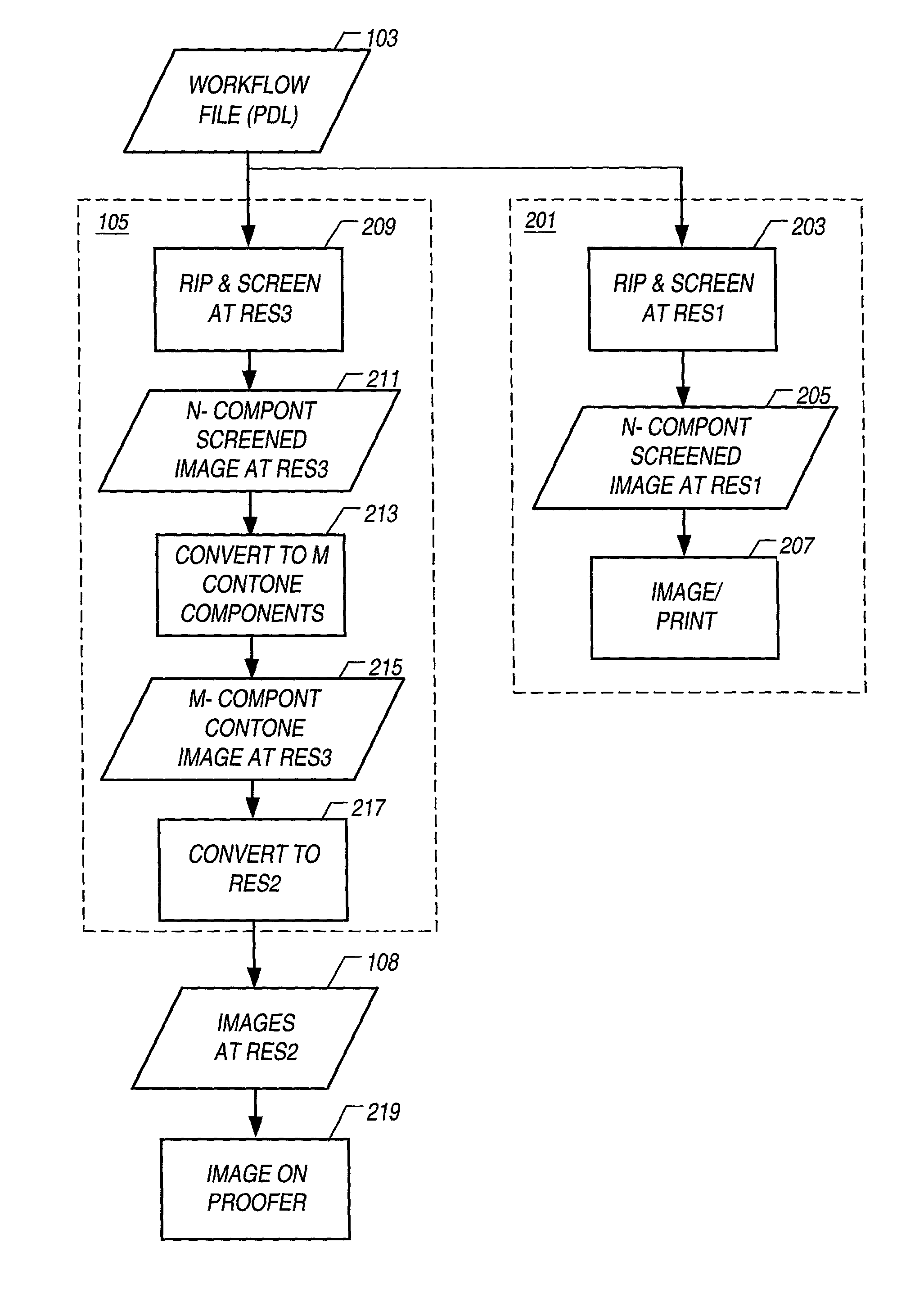
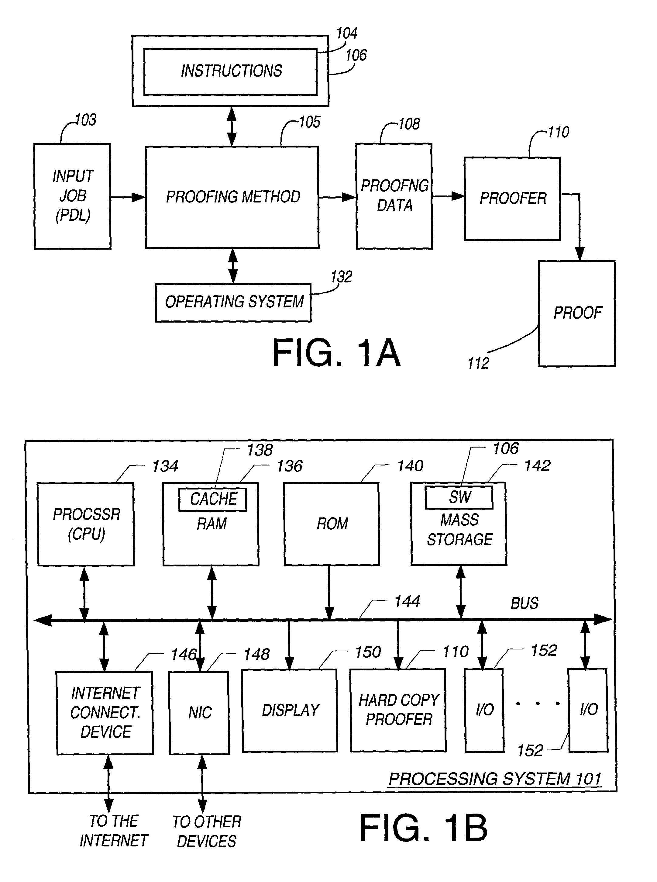
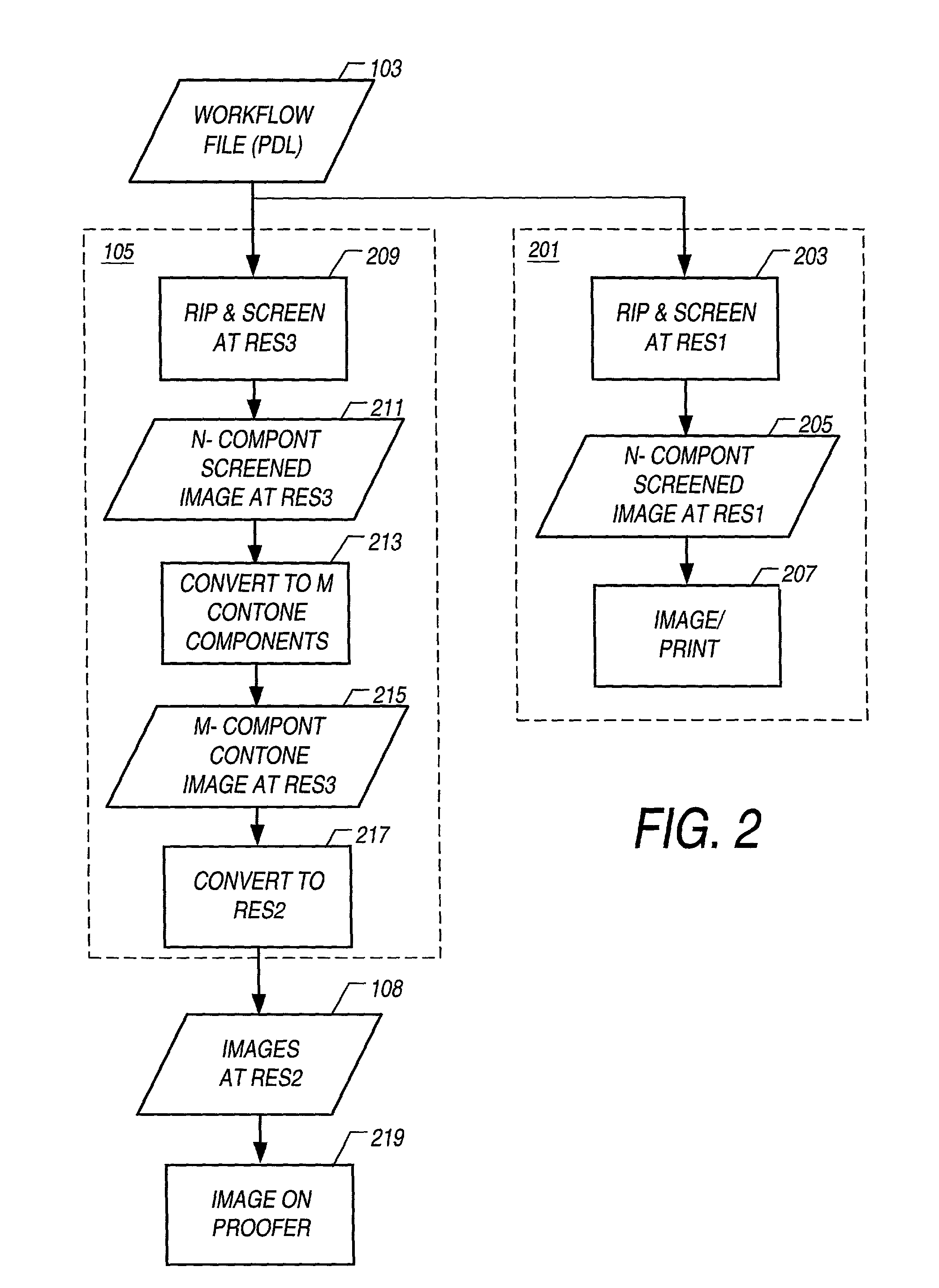
[0061]Referring to FIG. 1A, one embodiment is a proofing method 105 that operated on an input 103. Note that a “method for proofing,” a “method to proof,” and a “proofing method” herein each refers to preparing the data for output on a proofing device, and also to the combination of the steps of preparing the data for output on a proofing device and generating the proof on the proofing device. The input 103 may be a job 103 for proofing provided as a Page Description Language (PDL) file 103 for output printing at a printing resolution, denoted herein as RES1, which typically is expressed in dots per inch (dpi). The process of producing final output from the input 103 is called “output imaging” herein. The output imaging typically includes imaging on a film or plate for final printing on a printing press. The input 103 is assumed to be defined in a number of base colors, and this number is denoted by B herein. The final printing of the output imaging, e.g., on the printing press, use...


PUM


Abstract

A method, apparatus, and computer software product to reproduce an input image on a proofing device including accurately reproducing color substantially matching the screening properties of an imaging process that includes screening. The proofer may use a different number of colorants and / or different colorants than the printing colorants of the imaging process. The proofer also may be capable of continuous tone output or may be a screened output device. The proofer also may be a computer screen.

Description

RELATED U.S. APPLICATION[0001]This application claims the benefit of Provisional Patent Application Ser. No. 60 / 188,929, filed Mar. 8, 2000, entitled “PROOFING METHOD MATCHING COLOR AND HALFTONE SCREEN PROPERTIES”. Provisional Patent Application Ser. No. 60 / 188,929 is incorporated herein by reference.BACKGROUND OF THE INVENTION[0002]Several of the popular printing techniques such as offset, flexography, and gravure are rapidly being modified to accommodate computer-to-plate (also called “direct imaging”) technology according to which the final image carrier is made without the use of one or more intermediate films. Computer-to-plate technology offers savings in manpower, material (film) and environmental costs. One drawback of direct imaging technology is proofing.[0003]Traditionally, approval / acceptance of jobs prior to printing is mostly done by proofing using special proofing sheets such as Cromalin® or WaterProof® proofing sheets (E. I. du Pont de Nemours and Company). These pro...

Claims


Application Information

Patent Timeline
Patent Type & Authority Patents(United States)
IPC IPC(8): G06K1/00G06K15/00H04N1/60
CPCH04N1/6052H04N1/6011
Inventor DEWITTE, HANSPLETTINCK, LIEVEN C. G.
Owner BARCO GRAPHICS
Why Eureka
Try Eureka