Wireless communication device with two internal antennas
- Summary
- Abstract
- Description
- Claims
- Application Information
AI Technical Summary
Benefits of technology
Problems solved by technology
Method used
Image
Examples
first embodiment
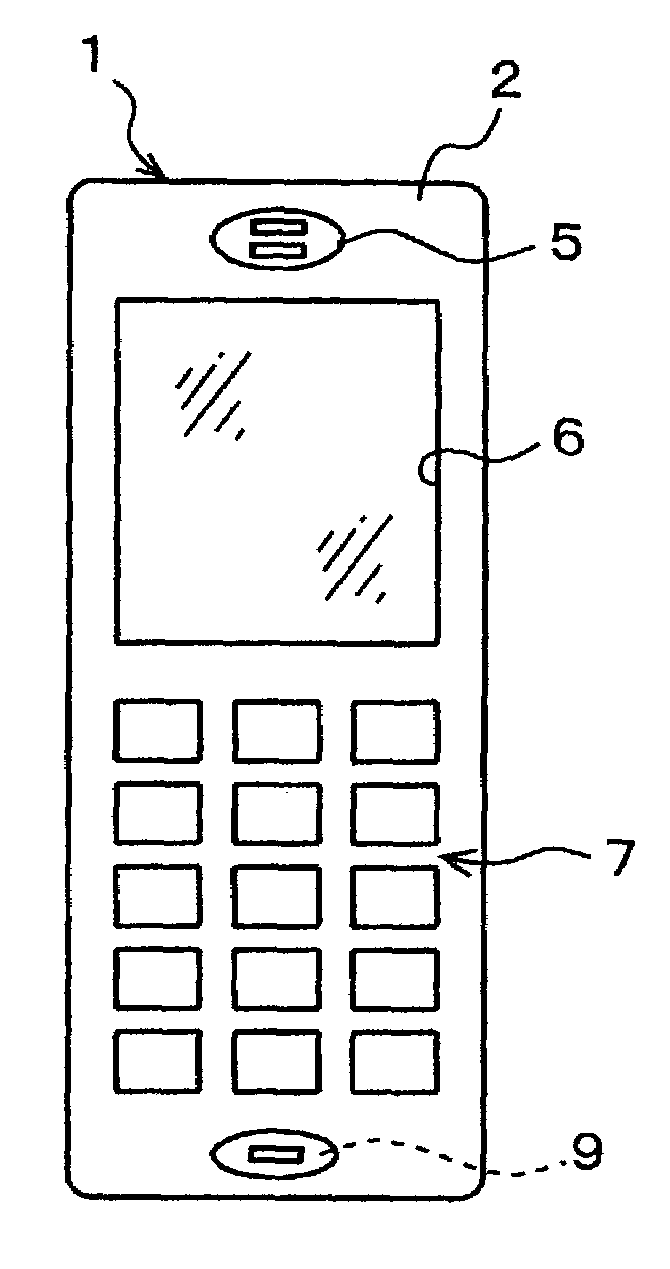
[0067]The invention will now be described in detail by way of example with reference to the accompanying drawings. FIG. 15A is a front view of a portable wireless communication terminal device according to the invention. FIG. 15B is a sectional side view thereof. FIG. 15C is a schematic diagram for showing a configuration of a built-in printed circuit board.
[0068]The portable wireless communication terminal device 1 of FIG. 15A is preferably applied to a stick type cellular phone, a foldable cellular phone and the like each having a data communication function and a telephone function. The device 1 has a casing of a predetermined configuration. The casing includes a front panel 2 and a rear panel 3. The upper section of the front panel 2 includes a receiver 5 for allowing a user to hear voice of a caller, and an opening window 6 for displaying various kinds of information. For this reason, attached to the opening window 6 is a liquid crystal display (LCD) 12 as an example of display...
third embodiment
[0108]Next, steps of folding the portable wireless communication terminal device 53 will now be described. FIGS. 26A–26D are respective perspective views of the portable wireless communication terminal device according to the invention, each showing how the device can be folded (closed) in accordance with first to fourth steps. First, when the portable wireless communication terminal device 53 is open as shown in FIG. 26A, the upper casing 36′ rotates on the pivot 54 through 90 degrees in the clockwise direction. This will bring the upper casing 36′ to an upright position as shown in FIG. 26B.
[0109]By further rotating the upper casing 36′ about the pivot 54 through 90 degrees in the clockwise direction, the upper casing 36′ is turned over, as shown in FIG. 26C. Then, under this condition, the upper casing 36′ and the pivot 54 are rotated together forward through 180 degrees by rotating the hinge section 38 until they abut against the lower casing 37. The portable wireless communicat...
second embodiment
[0114]This antenna-switching detection means 57 detects an antenna-switching request for switching between the first and second built-in antennas 47 and 48 and sends the detected results to the antenna selection switch 58. According to the antenna selection switch 58, either the first built-in antenna 47 or the second built-in antenna 48 is selected based on the antenna-switching request signal received from the antenna-switching detection means57, thereby allowing the corresponding antenna to be operated. Except for the antenna selection switch 58, the remaining members are the same as the ones of the portable wireless communication terminal device 35 described above as the second embodiment, as shown in FIGS. 23A and 23B, so that further details of the terminal device 56 will be omitted.
[0115]FIG. 28 is a diagram for explaining operations of an antenna-switching detection means of the portable wireless communication terminal device 56. The embodiment shown herein is based on the p...
PUM
 Abstract
Description
Claims
Application Information
 - R&D
- Intellectual Property
- Life Sciences
- Materials
- Tech Scout
- Unparalleled Data Quality
- Higher Quality Content
- 60% Fewer Hallucinations
Browse by: Latest US Patents, China's latest patents, Technical Efficacy Thesaurus, Application Domain, Technology Topic, Popular Technical Reports.
© 2025 PatSnap. All rights reserved.Legal|Privacy policy|Modern Slavery Act Transparency Statement|Sitemap|About US| Contact US: help@patsnap.com


