Air conditioning apparatus for hydraulic shovel

a technology of hydraulic shovels and air conditioning apparatuses, which is applied in the direction of vehicle heating/cooling devices, soil shifting machines/dredgers, transportation and packaging, etc., can solve the problems of air conditioning apparatus, narrow space inside the cab, and long ducts connecting air conditioning apparatuses and specific blow ports, so as to improve air conditioning efficiency and the like, the life of the outside air filter can be increased, and the inclusion is less.

Inactive Publication Date: 2006-07-04
KOMATSU LTD
View PDF13 Cites 15 Cited by
  • Summary
  • Abstract
  • Description
  • Claims
  • Application Information

AI Technical Summary

Benefits of technology

[0014]According to the above constitution, the vicinity of the vent hole provided at the upper region from the external cover, on the right side wall surface of the cab is located at the position substantially center of the vehicle, and therefore the air introduced from this vent hole has less inclusion of dust, and is less influenced by the rise in the temperature by warmed air after cooling the engine, and therefore preferable air for air conditioning can be introduced. As a result, the life of the outside air filter can be increased, and the air conditioning efficiency and the like can be enhanced.

Problems solved by technology

However, the above-described conventional air conditioning apparatus has the following problems.
However, when the wind distribution duct is placed inside the cab, there arises the problem that a space inside the cab becomes narrow by the amount of the duct space.
Further, there arises the problem that the ducts for connecting the air conditioning apparatus and specific blow ports become long.
Consequently, it takes time to perform a placement operation of these ducts, and this becomes the factor to increase the manufacturing cost.

Method used


Image

  • Air conditioning apparatus for hydraulic shovel
  • Air conditioning apparatus for hydraulic shovel
  • Air conditioning apparatus for hydraulic shovel

Examples


Embodiment Construction

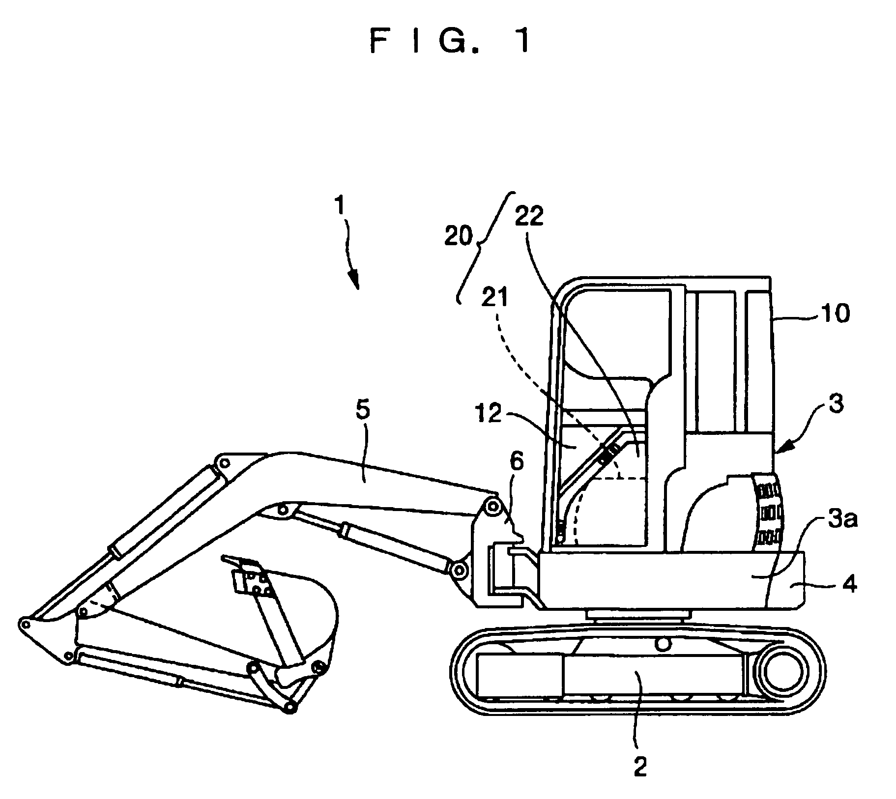
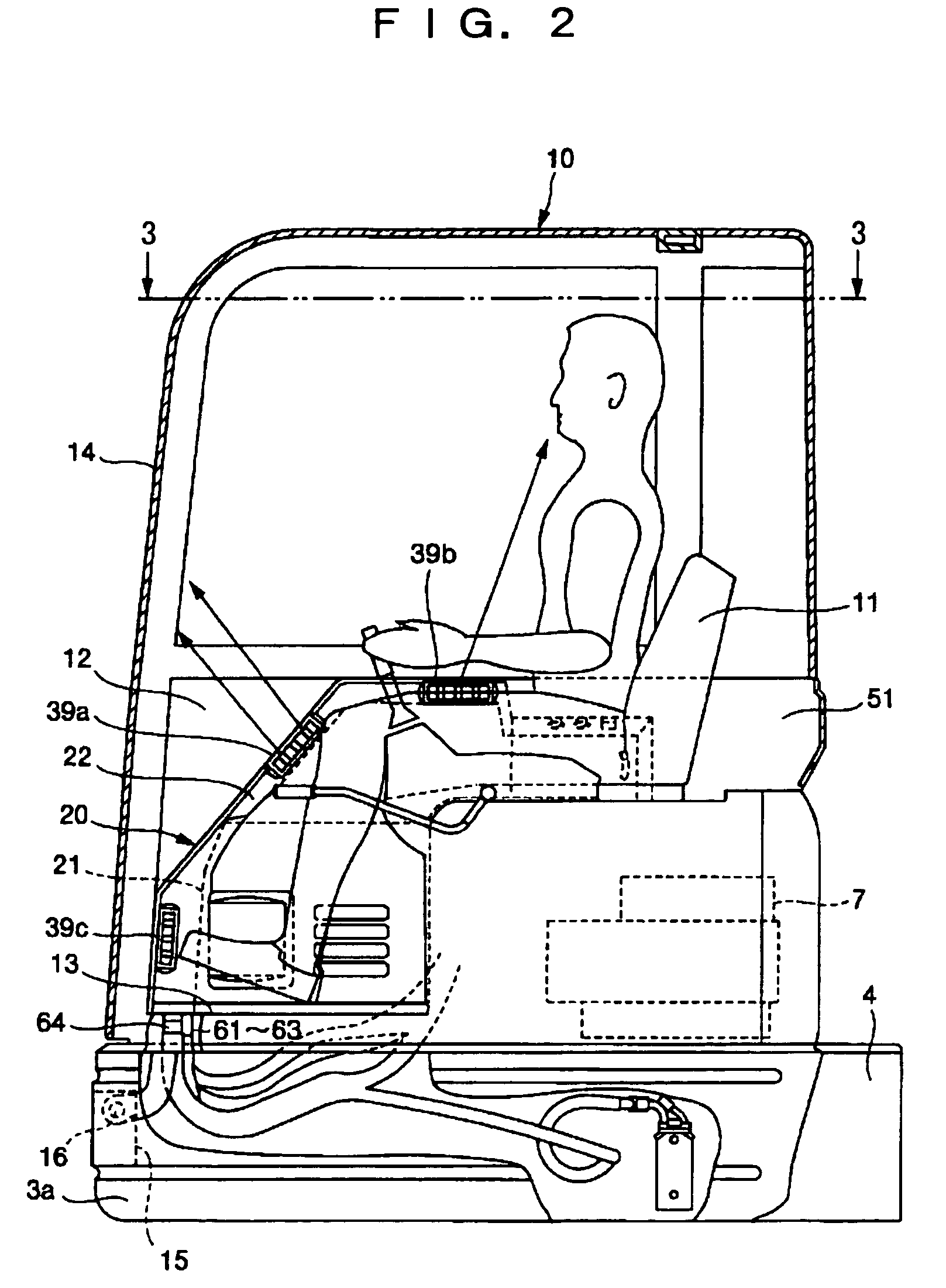
[0026]A preferred embodiment of the present invention will be explained in detail hereinafter with reference to the drawings. First, a general constitution of a rear ultrasmall revolving type hydraulic shovel, which is an example of a machine to which the present invention is applied, will be explained according to FIGS. 1 to 3.

[0027]In FIGS. 1 to 3, a hydraulic shovel 1 is loaded with an upper revolving superstructure 3 rotatably on a base carrier 2, and is provided with a cab 10 from a central portion of a front portion to a left end portion of a revolving frame 3a included at a lower portion of the upper revolving superstructure 3, and a counterweight 4 is mounted on a rear end portion of the revolving frame 3a. The cab 10 is connected to a bracket 15 provided at a front end portion of the revolving frame 3a to be swingable in a longitudinal direction via a horizontal pin 16, and is tiltable at a predetermined angle around the horizontal pin 16. An engine 7 is provided under an o...


PUM


Abstract

An air conditioning apparatus for a hydraulic shovel with which a wide space in a cab can be secured and a placement operation of ducts for distributing wind to each important point in the cab is facilitated. For this purpose, in the air conditioning apparatus, an air-conditioning unit (21) is placed at a front portion of a right side in a cab (10). The air-conditioning unit (21) is mounted to a front portion of a right side wall surface (51) of the cab (10). The air-conditioning unit (21) is mounted to the right side wall surface (51) of the cab (10) to be capable of being taken in and out from an inside and an outside of the cab (10).

Description

TECHNICAL FIELD[0001]The present invention relates to an air conditioning apparatus which is installed in a cab of a hydraulic shovel.BACKGROUND ART[0002]There is a kind of construction equipment such as a hydraulic shovel including a cab which is made by enclosing an area around a cab scat by a door for getting on and off and wall surfaces having windows, and is provided with a working machine operating device and a traveling control device therein. Many units of equipment, in which air conditioning apparatuses are placed in the cabs for the purpose of improving operability (defroster for window glasses, and the like) and improving habitability (cooling and heating, air conditioning), are used in recent years. Conventionally, an air conditioning apparatus is placed, for example, between an operator seat and a rear wall surface of a cab (for example, see page 3 and FIG. 1 of Japanese Patent Laid-open No. 8-183323), on a rear wall portion of a cab or a floor surface under the operato...

Claims


Application Information

Patent Timeline
Patent Type & Authority Patents(United States)
IPC IPC(8): B60H1/32E02F9/16B60H1/00
CPCB60H1/00378
Inventor KAMIMAE, TAKESHIUI, KUNIO
Owner KOMATSU LTD
Why Eureka
Try Eureka