
Annular clean metal casting mold

a metal casting mold and clean technology, applied in the direction of manufacturing tools, foundry patterns, foundry moulding apparatus, etc., can solve the problems of metal not being able to be obtained with a high quality, the two possibilities are not what they are, and the segregation and inclusions in this area are difficult to be removed

Inactive Publication Date: 2014-08-26
HENAN XINGZHI PATENT SERVICE CO LTD
View PDF8 Cites 0 Cited by
  • Summary
  • Abstract
  • Description
  • Claims
  • Application Information

AI Technical Summary

Benefits of technology

This approach produces high-quality metal with fewer inclusions, reduces energy consumption, and eliminates the need for costly secondary refining, enabling efficient production of large annular or tubular metal pieces with improved yield and reduced environmental impact.

Problems solved by technology

The segregates and inclusions in this area are hard to be removed because of being located in the upper central portion.
However, both of the two possibilities are not what desired.
Currently, most of metal ingots in the world are still casted in this way, and thus a lot of metal cannot be got with a high quality and cannot to be used effectively and fully, which cause much energy wasting.
This causes a great wasting of manpower and resource.
Additionally, a great pressure is also imposed on the environment.
This does not meet the development requirements of energy saving and environmental protection, which is the great loss of the metal smelting industry.
In addition, because the efficiency is particularly low, especially the electric arc could seriously damage the crystallizer, a crystallizer mold in the manner of electroslag furnace remelting can only refine scores of furnace of steel, which increases the cost of production.
However, if the desired product needs a larger hole, more time and energy will be required for punching and reaming, which leads to the increasing of production cost.

Method used


Image

  • Annular clean metal casting mold
  • Annular clean metal casting mold
  • Annular clean metal casting mold

Examples


embodiment 1

[0022

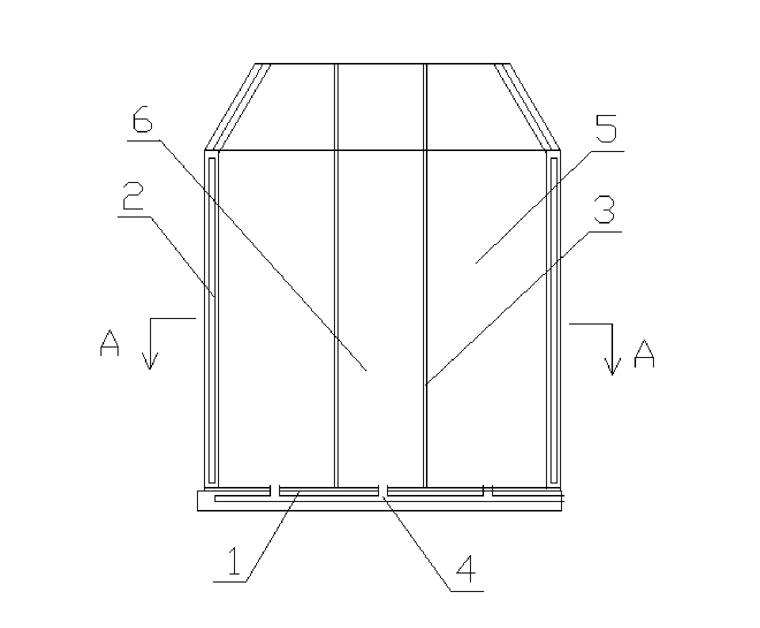
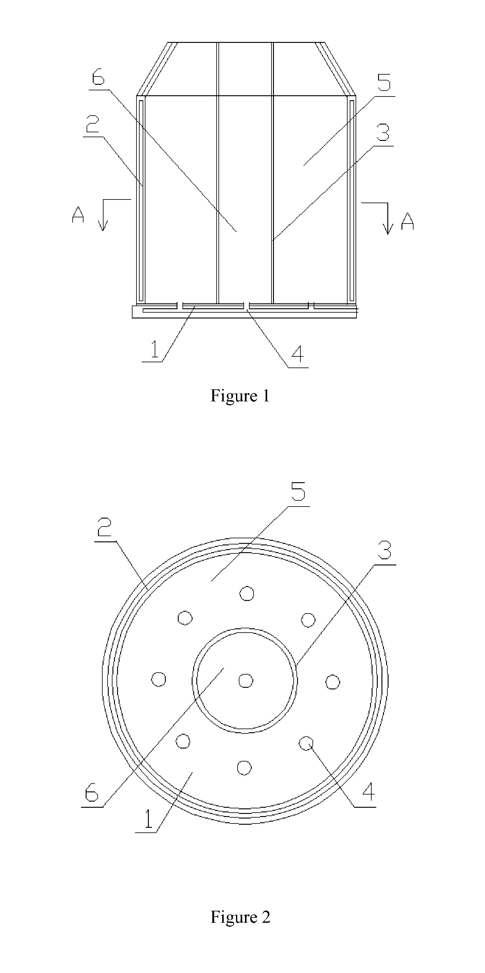
[0023]As shown in FIGS. 1 and 2, the annular clean metal casting mold includes a casting mold body with an ingate 4 and a heat preservation dead head arranged on the ingot mold body. The mold body have a cylindrical shape.

[0024]The casting mold body includes a cold bottom mold plate 1 and the peripheral cold mold plate 2 in connection with the cold bottom mold plate 1. An annular hot preservation layer 3 is disposed inside the peripheral cold mold plate 2. A cyclic clean crystalline region 5 is formed between the peripheral cold mold plate 2 and the annular hot preservation layer 3. The sacrificial crystalline region 6 is formed inside the cyclic hot preservation layer 3.

[0025]The cold bottom mold plate 1 is a water-cooled mold plate.

[0026]The peripheral cold mold plate 2 is a water-cooled mold plate.

[0027]The annular hot preservation layer 3 includes the skeleton and the heat preservation material outside the skeleton,

embodiment 2

[0028

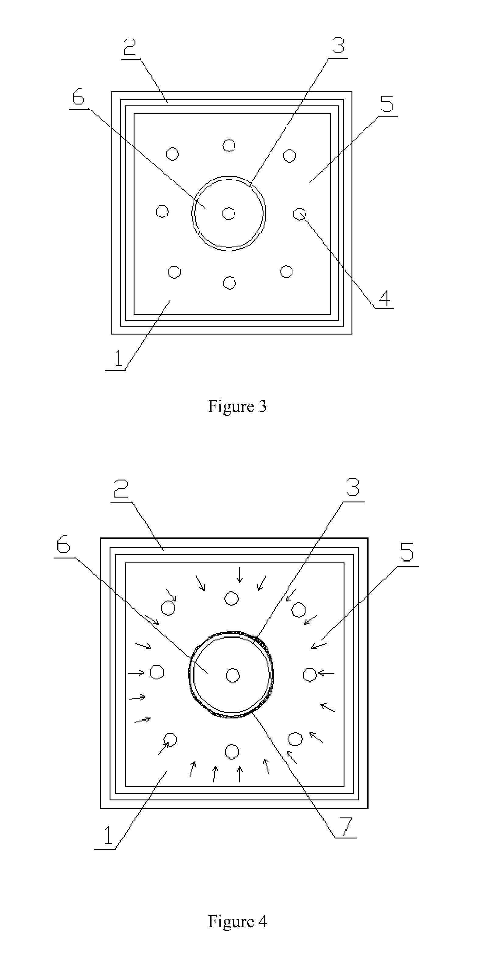
[0029]As shown in FIG. 3, the annular clean metal casting mold includes a casting mold body with an ingate 4 and a heat preservation dead head arranged on the ingot mold body.

[0030]The mold body has a cubic shape. The casting mold body includes the cold bottom mold plate 1 and the peripheral cold mold plate 2 in connection with the cold bottom mold plate 1. An annular hot preservation layer 3 is disposed inside the peripheral cold mold plate 2. A cyclic clean crystalline region 5 is formed between the peripheral cold mold plate 2 and the annular hot preservation layer 3. The sacrificial crystalline region 6 is formed inside the cyclic hot preservation layer 3.

[0031]The cold bottom mold plate 1 is a water-cooled mold plate.

[0032]The peripheral cold mold plate 2 is a water-cooled mold plate.

[0033]The annular hot preservation layer 3 includes the skeleton and the heat preservation material outside the skeleton.

[0034]As shown in FIG. 4, an annular hot preservation layer 3 is dispos...


PUM

PropertyMeasurementUnit
pressureaaaaaaaaaa
shapeaaaaaaaaaa
energyaaaaaaaaaa

Abstract

An annular clean metal casting mold has a mold body which includes a cold bottom mold plate and a peripheral cold mold plate in connection with the cold bottom mold plate. An annular hot preservation layer is disposed inside the peripheral cold mold plate. A cyclic clean crystalline region is formed between the peripheral cold mold plate and the annular hot preservation layer. A sacrificial crystalline region is formed inside the cyclic hot preservation layer. As the outer race of the annular clean crystallization zone contacts large area of the peripheral low cold mold plate, releasing heat rapidly, while the inner race contacts the annular hot preservation layer 3, heat dissipation is extremely slow, naturally result in forming orientational crystallization. The vast majority of impurities and segregations in the liquid metal are gathered at the portion contacting with the annular hot preservation layer, and thus after the liquid metal is solidified, the gathered impurities and segregations can be removed easily, to obtain a clean casting ingot.

Description

[0001]This application is a U. S. National Phase Application of PCT International Application PCT / CN2010 / 079037, filed on Nov. 24, 2010, which is based on and claims priority from CN 201010527822.7, filed on Oct. 26, 2010, the contents of which is incorporated in its entirety by reference.TECHNICAL FIELD[0002]The present invention relates to an annular clean metal casting mold which belongs to the field of metallurgical casting equipment technology.BACKGROUND OF THE INVENTION[0003]It is well known in the art that in the upper off-center position of the ingot casted by ordinary casting mold, there exists a V-shape area enriching of segregates and inclusions. The segregates and inclusions in this area are hard to be removed because of being located in the upper central portion. In this case, it leads to two possibilities: one is to ensure the quality of the metal by sacrificing more than half of the metal yield; the other one is to ensure certain metal yield by lowering its quality. H...

Claims


Application Information

Patent Timeline
Patent Type & Authority Patents(United States)
IPC IPC(8): B22C9/06B22D27/04
CPCB22C9/06B22C9/065B22D27/04B22D7/04B22D7/00B22D7/064B22D7/10B22D9/006B22D41/005
Inventor ZHU, SHUCHENGWANG, XIBINCAO, GUOCHAO
Owner HENAN XINGZHI PATENT SERVICE CO LTD
Learn More