Annular clean metal casting mold

a metal casting mold and clean technology, applied in the direction of manufacturing tools, foundry patterns, foundry moulding apparatus, etc., can solve the problems of metal not being able to be obtained with a high quality, the two possibilities are not what they are, and the segregation and inclusions in this area are difficult to be removed

Inactive Publication Date: 2013-10-17
HENAN XINGZHI PATENT SERVICE CO LTD
View PDF3 Cites 0 Cited by
  • Summary
  • Abstract
  • Description
  • Claims
  • Application Information

AI Technical Summary

Benefits of technology

[0014]As for the annular clean crystallization zone, its outer race contacts the large area of the peripheral cold mold plate, releasing heat rapidly; and the inner race contacts the annular hot preservation layer. As the heat dissipation of sacrificial crystallization zone in the annular hot preservation layer is extremely slow, the inner race presents a high temperature in its vicinity, which naturally results in forming orientational crystallization of the liquid metal from the outer race towards the inner race. During the process of crystallization, the inclusions and segregates in the liquid metal will be driven to the direction of annular hot preservation layer, and the liquid metal near the annular hot preservation layer solidifies at last because of being away from low temperature, and most of the inclusions and segregates in the liquid metal are enriched at the portion in contacts with the annular hot preservation layer. In this way, it will be very easy to use flame or other processing methods to remove th

Problems solved by technology

The segregates and inclusions in this area are hard to be removed because of being located in the upper central portion.
However, both of the two possibilities are not what desired.
Currently, most of metal ingots in the world are still casted in this way, and thus a lot of metal cannot be got with a high quality and cannot to be used effectively and fully, which cause much energy wasting.
This causes a great wasting of manpower and resource.
Additionally, a great pressure is also imposed on the environment.
This does not meet the development requir

Method used


Image

  • Annular clean metal casting mold
  • Annular clean metal casting mold
  • Annular clean metal casting mold

Examples


embodiment 1

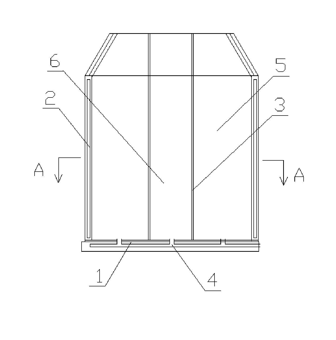
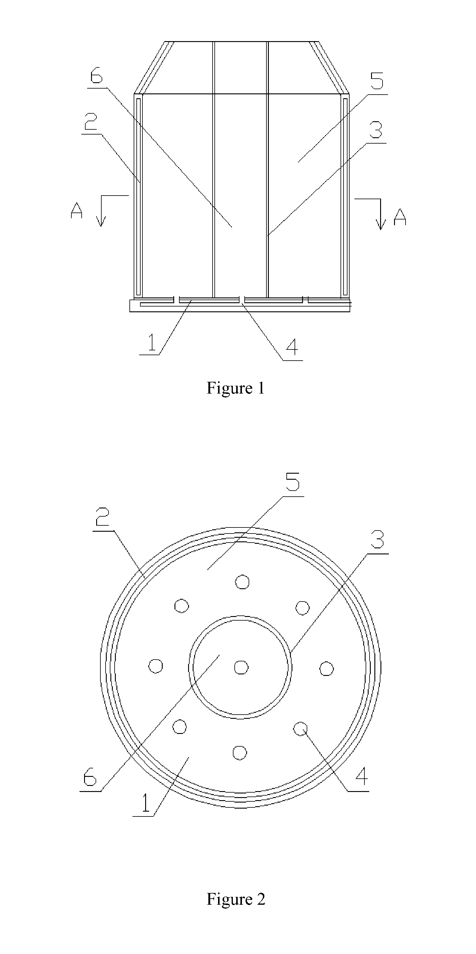
[0021]As shown in FIGS. 1 and 2, the annular clean metal casting mold includes a casting mold body with an ingate 4 and a heat preservation dead head arranged on the ingot mold body. The mold body have a cylindrical shape.

[0022]The casting mold body includes a cold bottom mold plate 1 and the peripheral cold mold plate 2 in connection with the cold bottom mold plate 1. An annular hot preservation layer 3 is disposed inside the peripheral cold mold plate 2. A cyclic clean crystalline region 5 is formed between the peripheral cold mold plate 2 and the annular hot preservation layer 3. The sacrificial crystalline region 6 is formed inside the cyclic hot preservation layer 3.

[0023]The cold bottom mold plate 1 is a water-cooled mold plate.

[0024]The peripheral cold mold plate 2 is a water-cooled mold plate.

[0025]The annular hot preservation layer 3 includes the skeleton and the heat preservation material outside the skeleton,

embodiment 2

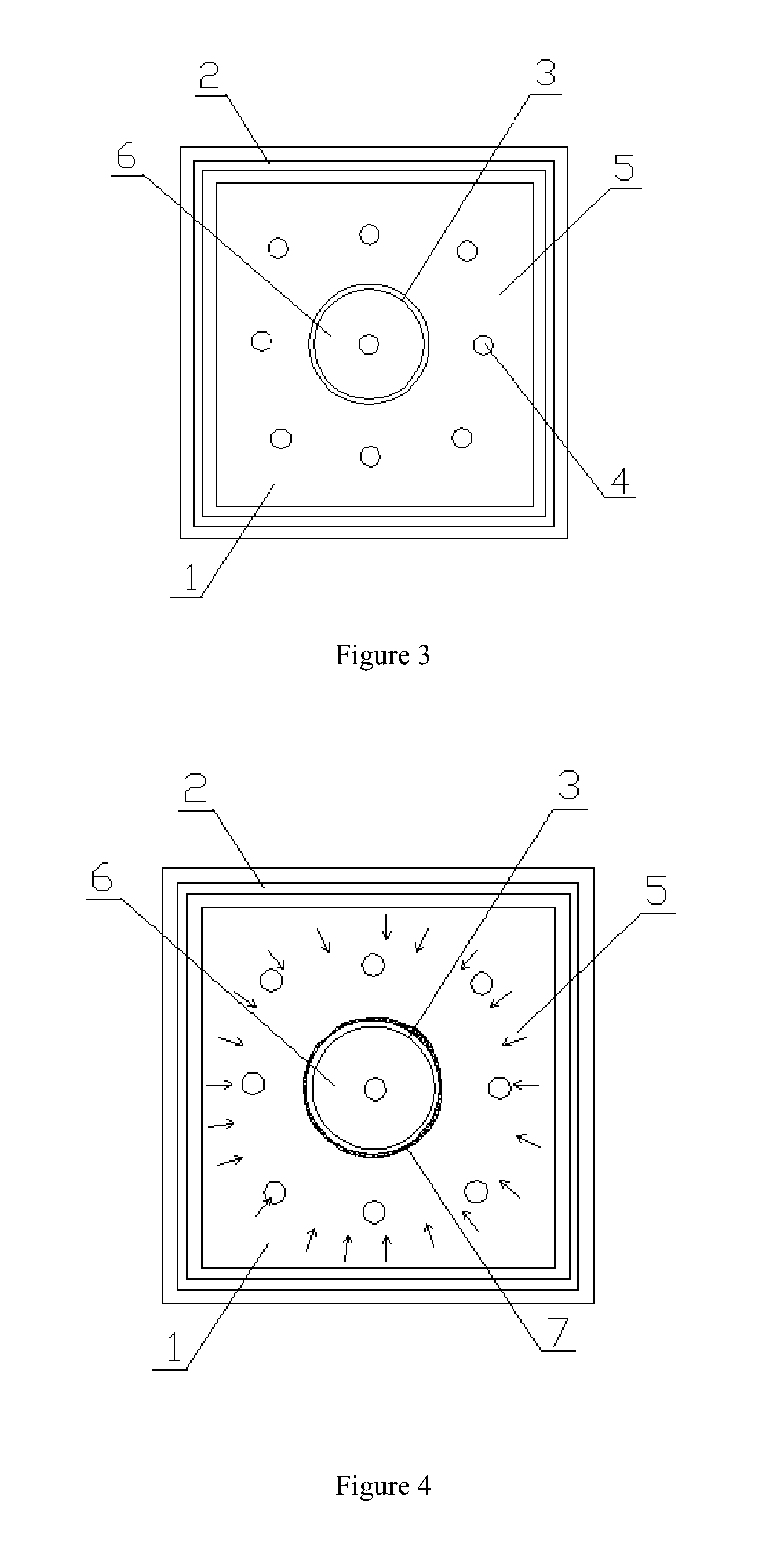
[0026]As shown in FIG. 3, the annular clean metal casting mold includes a casting mold body with an ingate 4 and a heat preservation dead head arranged on the ingot mold body.

[0027]The mold body has a cubic shape. The casting mold body includes the cold bottom mold plate 1 and the peripheral cold mold plate 2 in connection with the cold bottom mold plate 1. An annular hot preservation layer 3 is disposed inside the peripheral cold mold plate 2. A cyclic clean crystalline region 5 is formed between the peripheral cold mold plate 2 and the annular hot preservation layer 3. The sacrificial crystalline region 6 is formed inside the cyclic hot preservation layer 3.

[0028]The cold bottom mold plate 1 is a water-cooled mold plate.

[0029]The peripheral cold mold plate 2 is a water-cooled mold plate.

[0030]The annular hot preservation layer 3 includes the skeleton and the heat preservation material outside the skeleton.

[0031]As shown in FIG. 4, an annular hot preservation layer 3 is disposed in...


PUM


Abstract

An annular clean metal casting mold has a mold body which includes a cold bottom mold plate and a peripheral cold mold plate in connection with the cold bottom mold plate. An annular hot preservation layer is disposed inside the peripheral cold mold plate. A cyclic clean crystalline region is formed between the peripheral cold mold plate and the annular hot preservation layer. A sacrificial crystalline region is formed inside the cyclic hot preservation layer. As the outer race of the annular clean crystallization zone contacts large area of the peripheral low cold mold plate, releasing heat rapidly, while the inner race contacts the annular hot preservation layer 3, heat dissipation is extremely slow, naturally result in forming orientational crystallization. The vast majority of impurities and segregations in the liquid metal are gathered at the portion contacting with the annular hot preservation layer, and thus after the liquid metal is solidified, the gathered impurities and segregations can be removed easily, to obtain a clean casting ingot.

Description

TECHNICAL FIELD[0001]The present invention relates to an annular clean metal casting mold which belongs to the field of metallurgical casting equipment technology.BACKGROUND OF THE INVENTION[0002]It is well known in the art that in the upper off-center position of the ingot casted by ordinary casting mold, there exists a V-shape area enriching of segregates and inclusions. The segregates and inclusions in this area are hard to be removed because of being located in the upper central portion. In this case, it leads to two possibilities: one is to ensure the quality of the metal by sacrificing more than half of the metal yield; the other one is to ensure certain metal yield by lowering its quality. However, both of the two possibilities are not what desired.[0003]Currently, most of metal ingots in the world are still casted in this way, and thus a lot of metal cannot be got with a high quality and cannot to be used effectively and fully, which cause much energy wasting.[0004]And in or...

Claims


Application Information

Patent Timeline
IPC IPC(8): B22D27/04B22C9/06
CPCB22D27/04B22C9/065B22D7/00B22D7/064B22D7/10B22D9/006B22D7/04B22C9/06B22D41/005
Inventor ZHU, SHUCHENGWANG, XIBINCAO, GUOCHAO
Owner HENAN XINGZHI PATENT SERVICE CO LTD
Why Eureka
Try Eureka