
Light unit with heat dispensing device

a technology of heat dispensing device and light unit, which is applied in the direction of lighting and heating apparatus, semiconductor devices for light sources, and light support devices. it can solve the problems of reducing the life of leds and burning users at high temperature, and achieve the effect of quick release of hea

Inactive Publication Date: 2013-10-15
LIN TUNG HSIUNG
View PDF5 Cites 6 Cited by
  • Summary
  • Abstract
  • Description
  • Claims
  • Application Information

AI Technical Summary

Benefits of technology

The invention is a lighting fixture that has a heat-dispersing device. The device helps to quickly release the heat generated by the lighting components. The technical effect of this invention is to help prevent overheating and improve the overall performance of the lighting fixture.

Problems solved by technology

However, the conventional shade does not have good heat dispensing feature so that the shade traps the heat in the shade and the high temperature of the shade may burn the users.
The high temperature may reduce the life of the LEDs.

Method used


Image

  • Light unit with heat dispensing device
  • Light unit with heat dispensing device
  • Light unit with heat dispensing device

Examples


Embodiment Construction

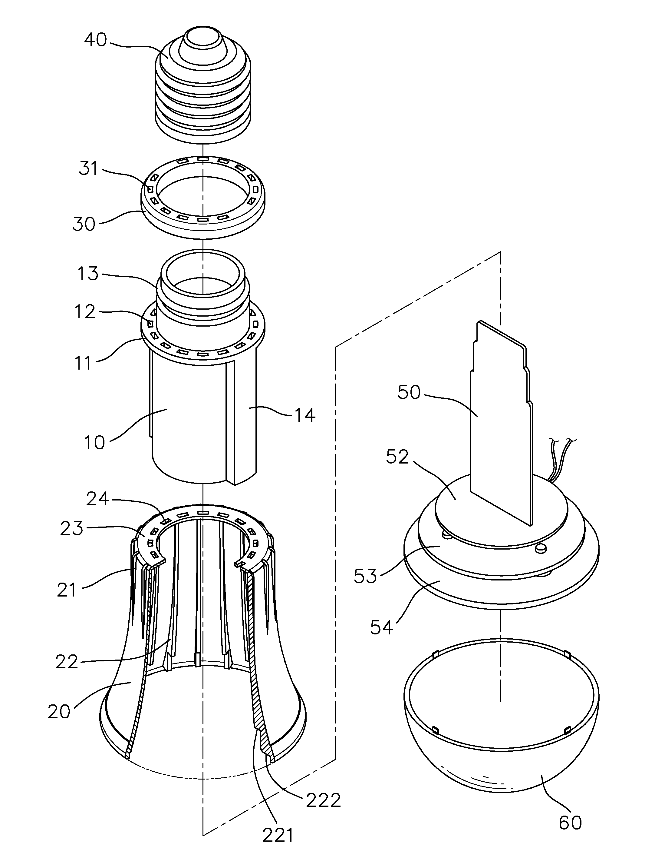
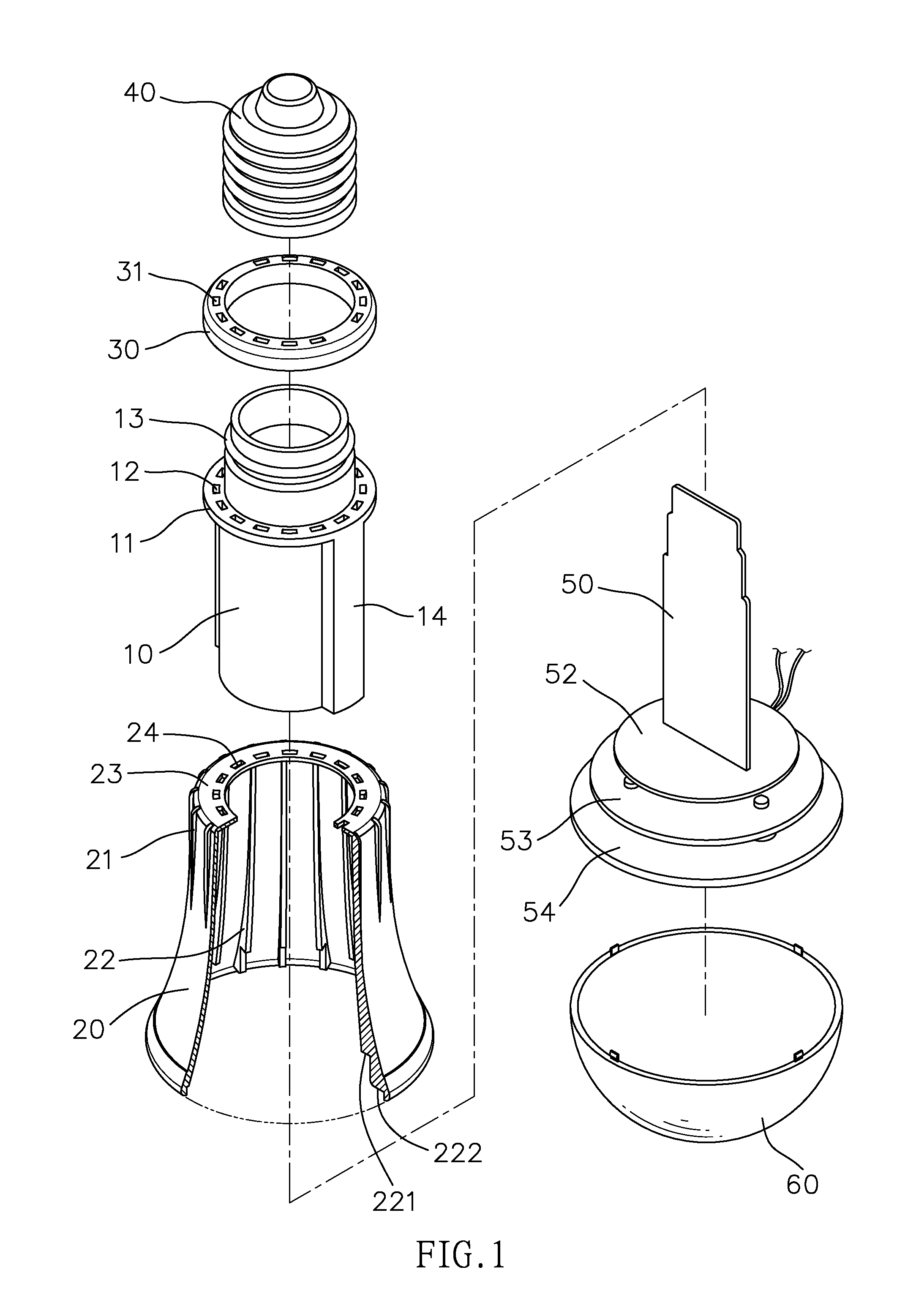
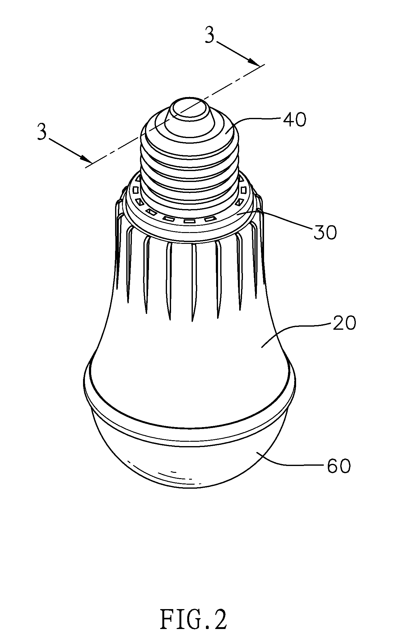
[0018]Referring to FIGS. 1 to 5, the light unit of the present invention comprises a tubular part 10 having a flange 11 extending outward from the outside thereof and multiple First holes 12 are defined through the flange 11. A shade 20 is mounted to the tubular part 10 and has outer tins 21 on the outside thereof. Multiple inner tins 22 are located on the inside of the shade 20. A lip 23 extends inward from the periphery of the top opening of the shade 20. The lip 23 has second holes 24 which are located corresponding to the first holes 12. When the shade 20 is mounted to the tubular part 10, the lip 23 is rested on the flange 11.

[0019]A collar 30 has third holes 31 which are located corresponding to the second holes 24 of the shade 20. The collar 30 is mounted to the tubular part 10 and contacts the top of the collar 30. A connector 40 is fixed to the top of the tubular part 10.

[0020]A circuit board unit 50 has multiple lighting members 51 connected thereto. The circuit board unit...


PUM


Abstract

A light unit includes a tubular part, a shade, a collar, a connector, a circuit board unit and a cover. The tubular part has a flange with multiple first holes and multiple outer fins are located on the outside of the tubular part. A lip extends from the top opening of the shade and second holes are defined through the lip. The shade is mounted to the tubular part to rest the lip on the flange. The collar further has third holes and is mounted to the tubular part. The connector is fixed to the top of the tubular part and Light Emitting Diodes are connected to the circuit board unit and located in the tubular part. The cover is connected to the lower end of the shade. The heat generated by the Light Emitting Diodes is released via the first, second and third holes.

Description

FIELD OF THE INVENTION[0001]The present invention relates to light unit with a heat dispensing device, and more particularly, to a light heat with a heat dispensing device of high efficiency.BACKGROUND OF THE INVENTION[0002]A conventional light unit using Light Emitting Diodes (LEDs) is directly connected to the inside of the shade and the LEDs generate heat during operation. However, the conventional shade does not have good heat dispensing feature so that the shade traps the heat in the shade and the high temperature of the shade may burn the users. The high temperature may reduce the life of the LEDs.[0003]The present invention intends to provide a light unit with a heat dispensing device and the heat dispensing device improves the shortcomings of the conventional light units.SUMMARY OF THE INVENTION[0004]The present invention relates to a light unit and comprises a tubular part having a flange extending, outward from the outside thereof and multiple first holes are defined throu...

Claims


Application Information

Patent Timeline
Patent Type & Authority Patents(United States)
IPC IPC(8): F21V29/00
CPCF21K9/1355F21V29/74F21V29/507F21K9/1375F21V3/02F21V23/006F21V29/83F21K9/23F21Y2115/10F21K9/238
Inventor LIN, TUNG-HSIUNG
Owner LIN TUNG HSIUNG
Learn More