Fuel cell stack and fuel cell system having the same

a fuel cell and stack technology, applied in the field of stacks of fuel cell systems, can solve the problems of fuel cell damage, inability to effectively cool all unit cells of the stack, and deterioration of the electrolyte membrane performance, and achieve the effect of uniformly maintaining the temperature of the entire stack and quick release of heat generated

Inactive Publication Date: 2006-08-03
SAMSUNG SDI CO LTD
View PDF3 Cites 18 Cited by
  • Summary
  • Abstract
  • Description
  • Claims
  • Application Information

AI Technical Summary

Benefits of technology

[0014] The present invention is directed to a fuel cell system that is capable of quickly releasing heat generated from the entire stack and of uniformly maintaining the temperature of the entire stack within an appropriate range by changing the heat-emission structure depending on location within the stack.

Problems solved by technology

In such a fuel cell system, when the operating temperature deviates from an appropriate range, the performance of the electrolyte membrane deteriorates and safety thereof cannot be ensured.
Furthermore, in a serious case, the fuel cell may be damaged.
However, the adaptation of the same cooling scheme to all parts of the stack in a conventional cooling scheme makes it difficult to effectively cool all unit cells of a stack which may have substantially different temperature distributions depending on their positions within the stack.
In the conventional fuel cell system, since heat generated in each of the stacked unit cells is not uniformly released, the performance of the stack deteriorates, thereby decreasing the overall efficiency of the fuel cell system.

Method used


Image

  • Fuel cell stack and fuel cell system having the same
  • Fuel cell stack and fuel cell system having the same
  • Fuel cell stack and fuel cell system having the same

Examples


Embodiment Construction

[0060] Hereinafter, embodiments of the present invention will be described in detail with reference to the accompanying drawings such that the embodiments can be easily put into practice by those skilled in the art. However, since the present invention can be embodied in various forms, the present invention is not limited to the embodiments described below.

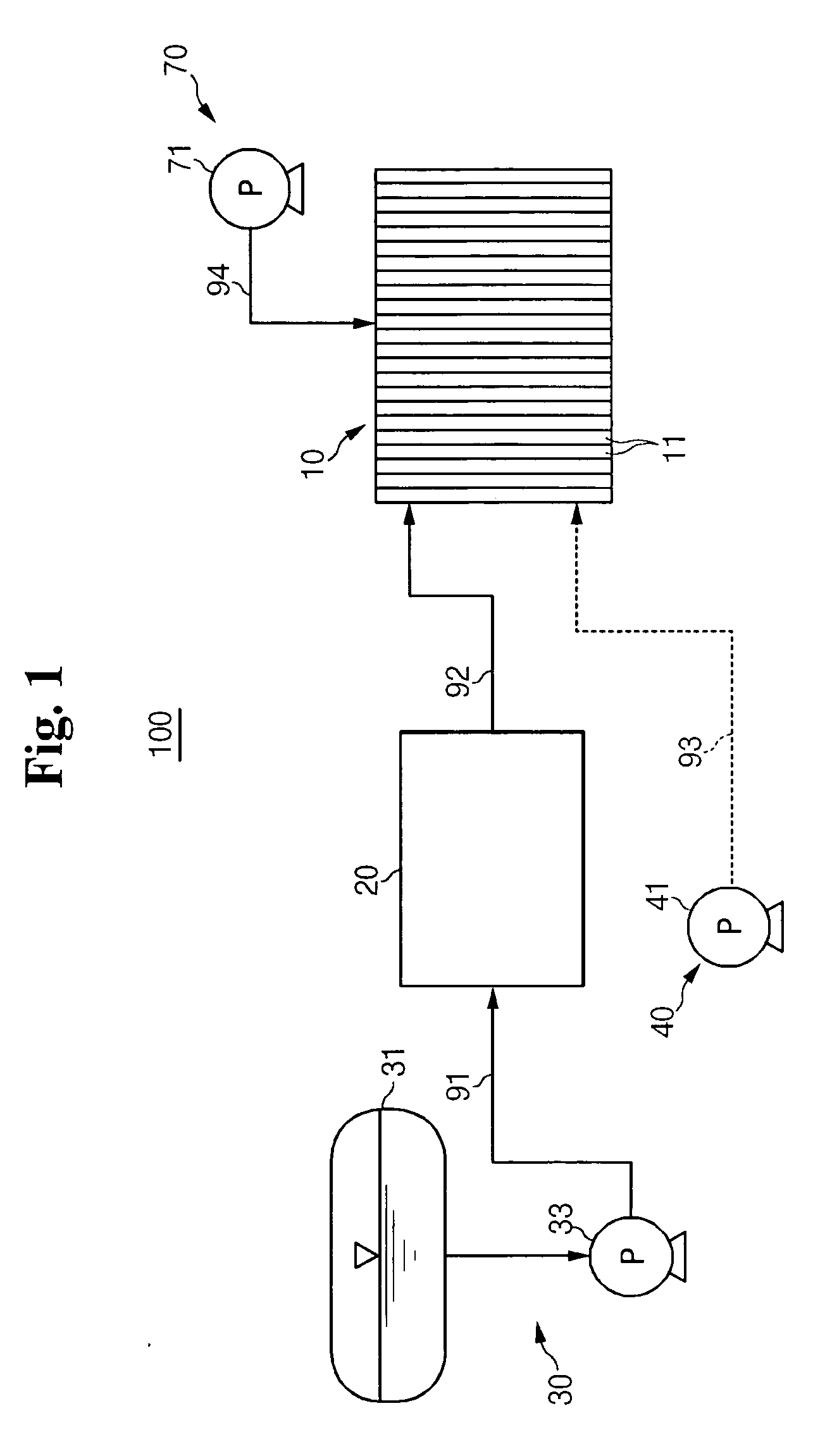
[0061]FIG. 1 is a schematic diagram illustrating a structure of a fuel cell system according to an embodiment of the present invention.

[0062] Referring to FIG. 1, the fuel cell system 100 according to the present invention comprises a stack 10 in which a number of electricity generators 11 for converting chemical energy into electric energy through a chemical reaction between hydrogen and oxygen are stacked, a fuel supply unit 30 for supplying the hydrogen-containing fuel to the electricity generators 11, an air supply unit 40 for supplying air to the electricity generators 11, and a coolant supply unit 70 for supplying a coolan...


PUM

PropertyMeasurementUnit
temperaturesaaaaaaaaaa

Abstract

There is provided a stack of a fuel cell system in which one or more electricity generators including separators disposed at both sides of a membrane-electrode assembly are stacked, the stack comprising heat releasing means for releasing heat generated from the electricity generators. The heat releasing means have different heat release rates depending on the positions of the associated electricity generators in the stack. In particular, the heat releasing means associated with the electricity generators located near the center of the stack have a higher heat release rate in order to maintain a more even temperature gradient across the stack.

Description

CROSS-REFERENCE TO RELATED APPLICATION [0001] This application claims priority to and the benefit of Korean Patent Application No. 10-2005-0007919, filed on Jan. 28, 2005 in the Korean Intellectual Property Office, the entire content of which is incorporated herein by reference. FIELD OF THE INVENTION [0002] The present invention relates to a fuel cell system, and more particularly to a stack of a fuel cell system with improved cooling efficiency, and a fuel cell system having the same. BACKGROUND OF THE INVENTION [0003] In general, a fuel cell is an electricity generating system for directly converting chemical energy into electric energy through an electrochemical reaction between oxygen contained in air and hydrogen contained in hydrocarbon-grouped materials such as methanol, ethanol, and natural gas. Specifically, fuel cells have a feature such that electricity is generated through an electrochemical reaction between a fuel gas and an oxidizing gas without combustion and with he...

Claims


Application Information

Patent Timeline
Patent Type & Authority Applications(United States)
IPC IPC(8): H01M8/04H01M8/24
CPCH01M8/0247H01M8/0267H01M8/04007H01M8/04074H01M8/1002H01M8/1011H01M8/241Y02E60/50H01M8/1007H01M8/2457H01M8/2483A47G21/00A47G21/045A47G2021/002H01M8/026H01M8/0265
Inventor SUH, JUN-WONKWEON, HO-JIN
Owner SAMSUNG SDI CO LTD
Why Eureka
Try Eureka