Ink jet recording head and recording apparatus

a recording apparatus and recording head technology, applied in printing and other directions, can solve the problems of inability to perform ejection itself, defect in recording image, and excessive energy corresponding to difference, and achieve the effect of quick release of heat accumulated in the recording element substrate, improving recording speed and lowering recording quality

Active Publication Date: 2009-04-23
CANON KK
View PDF1 Cites 9 Cited by
  • Summary
  • Abstract
  • Description
  • Claims
  • Application Information

AI Technical Summary

Benefits of technology

[0023]According to the present invention, by the beams provided to the supporting member for supporting the recording element substrate, it is possible to quickly release heat accumulated in the recording element substrate. For this reason, according to a recording apparatus of the present invention, even in the case where a continuous recording operation is performed, temperature rise of the recording element substrate is suppressed, so that it is possible to improve a recording speed without lowering a recording quality.

Problems solved by technology

Therefore, excessive energy corresponding to a difference between the electric energy and the released energy is gradually accumulated in the recording head as heat to increase a temperature of the recording head itself.
When the temperature exceeds a predetermined temperature range, an ink ejection state is started to be unstable, so that a defect can occur in a recording image.
In the worst case, ejection itself cannot be performed.
As a result, depending on a recording area for a recorded image, an image density varies or fog occurs, so that there is a possibility of an occurrence of an image which does not reach a usable quality.
For this reason, in the conventional ink jet recording head, a total amount of heat generation is far larger than an amount of heat release per unit time, so that it was difficult to realize continuous recording for a long time.
Therefore, in the recording apparatuses for that purpose, most of the recording apparatuses are based on the premise that the image quality is lowered to some extent, so that the image quality and the high-speed recording operation have not been realized compatibly.

Method used


Image

  • Ink jet recording head and recording apparatus
  • Ink jet recording head and recording apparatus
  • Ink jet recording head and recording apparatus

Examples


embodiment

[0072]In this embodiment, specific shapes of the first recording element substrate 1100 and the first plate 1200 will be described with reference to FIGS. 6(a) to 6(c).

[0073]First, shapes of the first recording element substrate 1100 and the first plate 1200 of a conventional ink jet recording head will be described with reference to FIGS. 14(a) and 14(b) and FIGS. 15(a) and 15(b). FIG. 14(a) shows a shape of the conventional first plate 1200 as seen from the recording material side. FIG. 14(b) is a sectional view showing structures of the first plate 1200 and the first recording element substrate 1100 taken along a D-D line shown in FIG. 14(a). In this case, a pitch P1 between two supply ports 1102 is ensured to some extent, so that a thickness of a partition wall 1200b can be sufficiently ensured correspondingly to the pitch P1. For this reason, the partition wall 1200b can be formed between adjacent supply flow passages 1200a of the first plate 1200. Heat accumulated at a portion...

first reference embodiment

[0083]In the above-described Comparative Embodiment, the supply flow passage of the first plate is not provided with the beam. In First Reference Embodiment, the supply flow passage of the first plate is provided with two beams equidistantly disposed with respect to a longitudinal direction of the supply flow passage. Comparison between this First Reference Embodiment and the above-described Embodiment of the present invention will be described with reference to FIGS. 8(a) and 8(b).

[0084]For convenience, in this First Reference Embodiment, members identical to those in Embodiment described above are represented by the same reference numerals or symbols and omitted from redundant explanation.

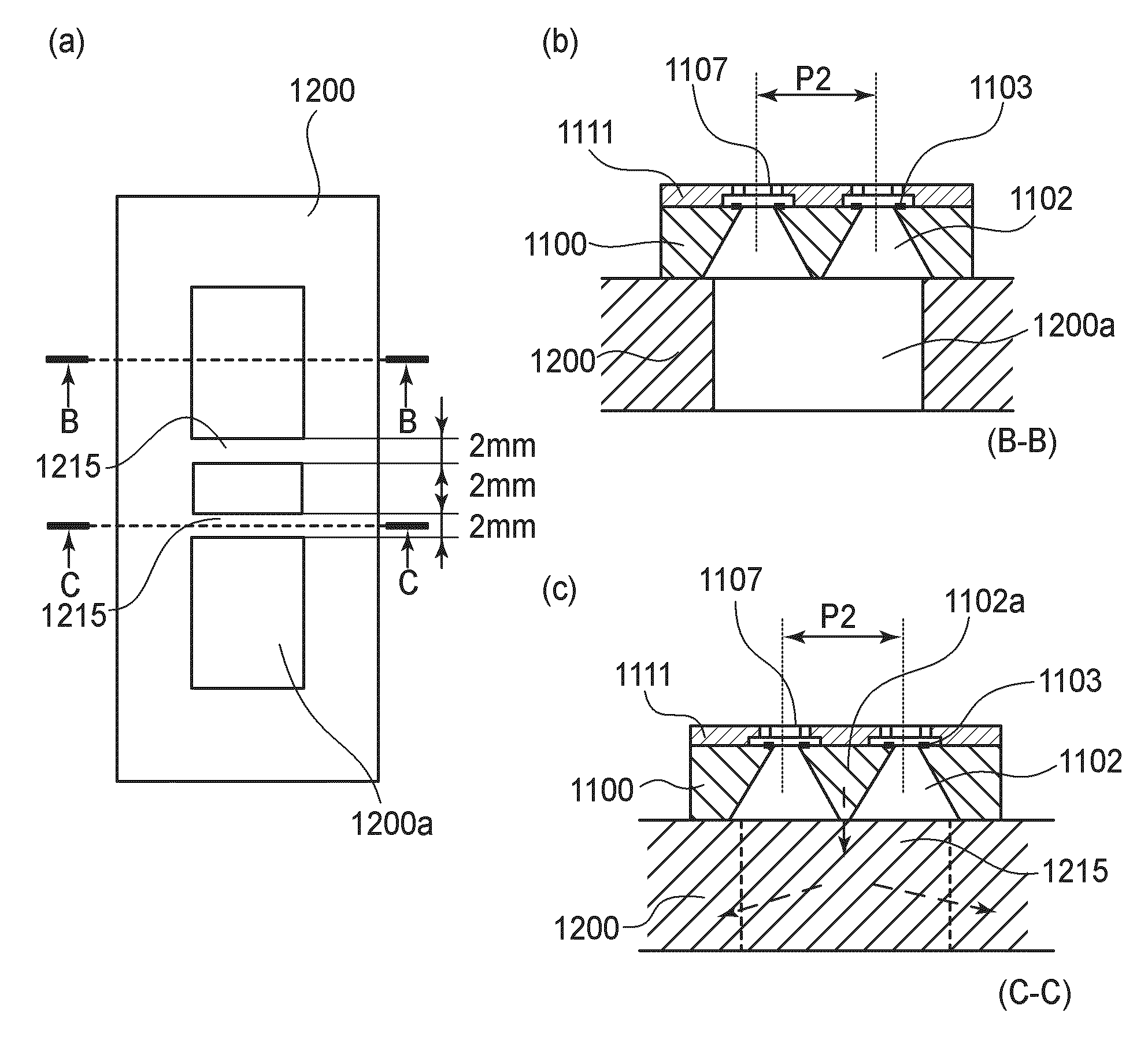
[0085]FIG. 8(a) is a plan view showing a temperature measuring point of the recording head in this First Reference Embodiment in which a first plate provided with two beams 1215 in a supply flow passage 1200 so that the two beams are equidistantly spaced from a center of the supply flow passage 1...

second reference embodiment

[0089]In the First Reference Embodiment, the supply flow passage of the first plate is provided with the two beams. In Second Reference Embodiment, the supply flow passage of the first plate is provided with a single wider beam disposed at a center of the supply flow passage with respect to a longitudinal direction of the supply flow passage. Comparison between this Second Reference Embodiment and the above-described Embodiment of the present invention will be described with reference to FIGS. 9(a) and 9(b).

[0090]FIG. 9(a) is a plan view showing a temperature measuring point of the recording head in this Second Reference Embodiment.

[0091]FIG. 9(b) is a graph showing a relationship between a temperature measured at the temperature measuring points shown in FIGS. 9(a) and 7(b) and a recording time.

[0092]As shown in FIG. 9(a), the recording head in this Second Reference Embodiment is provided with the first plate 1200 having the supply flow passage 1200a to which a single beam 1215 hav...


PUM


Abstract

An ink jet recording head is constituted by a recording element substrate including an ejection outlet array consisting of a plurality of arranged ejection outlets for ejecting ink; a plurality of heat generating elements, provided correspondingly to the ejection outlets, for generating thermal energy for ejecting the ink; and a supply port, formed along the ejection outlet array in an elongated hole-like shape, for supplying the ink to the ejection outlets; and a supporting member, having a supply flow passage communicating with the supply port, for supporting the recording element substrate. The supporting member is provided with at least two beams each extending over an opening of the supply flow passage in a widthwise direction of the supply flow passage and having a width W with respect to a longitudinal direction of the supply flow passage. At least two beams described above are disposed within a range from a center of the supply flow passage with respect to the longitudinal direction toward both longitudinal end sides of the supply flow passage by 2.5 W for each of the end sides and are spaced 2 mm or more apart.

Description

FIELD OF THE INVENTION AND RELATED ART[0001]The present invention relates to an ink jet recording head for ejecting ink and a recording apparatus for effecting recording on a recording material by using the ink jet recording head.[0002]Conventional recording apparatuses for effecting recording on a recording material such as paper or an OHP (overhead projector) sheet have been proposed in various forms such that recording heads adapted to various recording methods are mounted. These recording heads are of a wire dot type, a thermal type, a thermal transfer type, an ink jet type, and the like. Particularly, the ink jet type recording head directly ejects ink droplets onto the recording material, thus having advantages of a relatively low running cost, low noise, etc. Of this ink jet type recording head, a recording head of a recording type using electrothermal transducer elements is adapted to high-density image recording or high-speed recording and is put into practical use.[0003]In...

Claims


Application Information

Patent Timeline
Patent Type & Authority Applications(United States)
IPC IPC(8): B41J2/05
CPCB41J2/1404
Inventor TATSUMI, JUNJISAIKAWA, HIDEO
Owner CANON KK
Why Eureka
Try Eureka