Engine cooling systems

a technology for cooling systems and engines, applied in the direction of machines/engines, valve operating means/release devices, transportation and packaging, etc., can solve the problems of reducing the heat supply of the heater, absorbing the heat generated by the engine on start-up,

Inactive Publication Date: 2006-07-04
FORD GLOBAL TECH LLC
View PDF12 Cites 20 Cited by
  • Summary
  • Abstract
  • Description
  • Claims
  • Application Information

AI Technical Summary

Benefits of technology

[0006]Preferably, the common control valve is operable to prevent the auxiliaries return flow until the heater return flow reaches a first pre-determined temperature.

Problems solved by technology

It is a problem with such known arrangements that when the engine and the vehicle are both cold some of the heat generated by the engine on start-up is absorbed by the auxiliary heat exchangers.
Not only does the engine not warm up as quickly as it might but also the supply of heat to the heater is diminished because of the relatively slow warm up.

Method used


Image

  • Engine cooling systems
  • Engine cooling systems
  • Engine cooling systems

Examples


Embodiment Construction

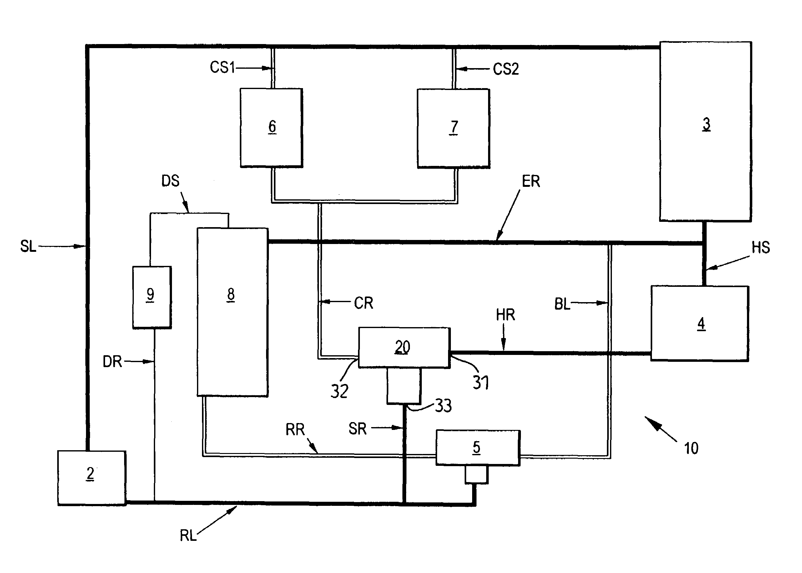
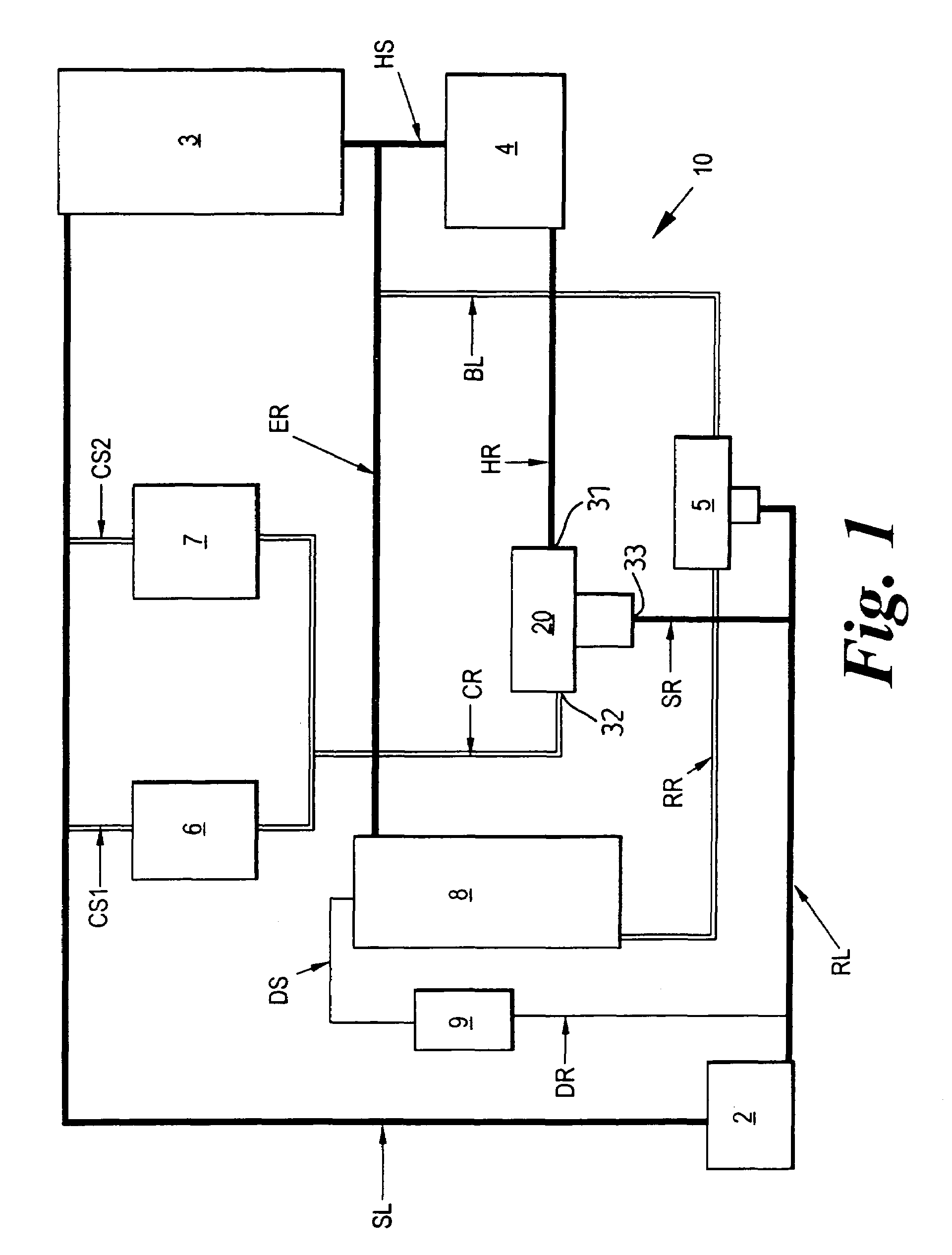
[0026]With particular reference to FIG. 1, a motor vehicle cooling system 10 comprises a primary cooling circuit having an air-cooled radiator 8 for cooling a liquid coolant for the engine 3. A pump 2 circulates the coolant through the engine 3 and then to the radiator 8 or to a bypass BL through an engine return line ER and back to the pump 2 through a primary flow control valve 5 and a pump return line RL. The primary flow control valve 5 is usually simply referred to as the thermostat. Here it will be referred to as the main thermostat 5 to avoid any confusion with other parts of the cooling system. An appropriate main thermostat 5 is described in EP-A-0794327 although conventional thermostats may be used. The bypass BL is arranged in parallel to the radiator 8 between the engine return line ER and the main thermostat 5. Coolant that has been cooled by the radiator 8 passes along a radiator return line RR to the main thermostat 5 and then back to the pump 2 through a pump return ...


PUM


Abstract

A heater diverter valve (20) is provided in an engine cooling system having a radiator and a circulating pump, The valve has a first inlet (31) connected to a heater so that coolant flowing through the engine and then through the heater is returned to the pump return line through the valve via the first inlet and an outlet (33). A second inlet (32) is connected to engine and transmission oil coolers so that coolant which flows from the engine supply line through the coolers is returned to the pump return line via the second inlet and the outlet. The valve includes a shuttle (24) which at lower coolant temperatures closes off the second inlet (32) to prevent coolant flow. The second inlet (32) is opened at higher temperatures when a wax type thermal actuator pushes the shuttle towards the first inlet (31).

Description

CROSS REFERENCE TO RELATED APPLICATIONS[0001]This application is a continuation of PCT International Patent Application No. PCT / GB02 / 03587 filed on 18 Aug. 2003, which is a continuation of GB 0220521.9, filed on 4 Sep. 2002 and claims benefit thereof.FIELD OF THE INVENTION[0002]This invention relates to engine cooling systems particularly, but not exclusively, for motor vehicles having a liquid cooled engine.BACKGROUND OF THE INVENTION[0003]It is well known to provide a motor vehicle with a cooling system in which a pump circulates coolant through the engine, through a radiator to cool the coolant and through a cabin heater which can use the coolant warmed by the engine to provide heating for the vehicle. It is also known to use the coolant to cool one or more auxiliary heat exchangers such as an engine oil cooler.[0004]It is a problem with such known arrangements that when the engine and the vehicle are both cold some of the heat generated by the engine on start-up is absorbed by t...

Claims


Application Information

Patent Timeline
Patent Type & Authority Patents(United States)
IPC IPC(8): F01P7/14F01P7/16F16K31/64
CPCF01P7/165F01P2037/02F01P2060/10F01P2060/045F01P2060/08F01P2060/04F01P7/16F01P2007/146
Inventor HUTCHINS, WILLIAM RICHARD
Owner FORD GLOBAL TECH LLC
Why Eureka
Try Eureka