Optical reader having inclinable stage which mounts optical unit thereon

a technology of optical units and optical readers, applied in the field of optical readers, can solve the problems of inefficient manufacturing and price increase, inability to generate optimal patterns to achieve prompt reading of objects, and different conventional longitudinal and lateral barcode scanners, etc., to achieve secure safety, improve reading reliance, and optimize scanning patterns

Inactive Publication Date: 2006-07-04
FUJITSU LTD
View PDF36 Cites 5 Cited by
  • Summary
  • Abstract
  • Description
  • Claims
  • Application Information

AI Technical Summary

Benefits of technology

[0018]It is another object of the present invention to provide an optical reader which maintains the optimal scanning pattern and has a high reading reliance.
[0019]It is still another object of the present invention to provide an optical reader that meets the laser safety standards and secures safety.

Problems solved by technology

However, the conventional longitudinal and lateral barcode scanners are different in manipulation and optimal scanning-pattern emitting directions.
Consequently, each barcode scanner, even for the same type, should be manufactured differently in emitting direction for every business type of different installation and usage environments, causing inefficient manufacturing and price increasing.
On the other hand, primarily for manufacturing purposes, there have been proposed apparatuses having a fixed emitting direction while the installation and usage environments are ignored, but these apparatuses cannot generate an optimal pattern to achieve an object of prompt reading.
Disadvantageous, each operator must adjust a barcode moving path and spend along time to master the operating skill.
Nevertheless, this invention was disadvantageous because it has a low reading reliance and does not always meet operative safety requirements.
The scanning pattern frequently used in this reference is not the actual optimal scanning as a result of simulation taking into account the arrangement between a laser source and a light receiving element, while minimizing optical noises caused by mirror angles and the light amount of the laser beam.
A scanning pattern including optical noises, even though hitting a barcode, cannot properly read the barcode data.
For instance, a certain mirror angle puts the reflected light over the store's light as a noise, and the light receiving element receives a large amount of incident light.
A laser beam reflected at an edge or the like of the reflection mirror also causes a large amount of light incident to the light receiving element.
However, the light amount of an arbitrarily changed scanning pattern would not necessarily meet the above standards, thereby endangering safety.

Method used


Image

  • Optical reader having inclinable stage which mounts optical unit thereon
  • Optical reader having inclinable stage which mounts optical unit thereon
  • Optical reader having inclinable stage which mounts optical unit thereon

Examples


Embodiment Construction

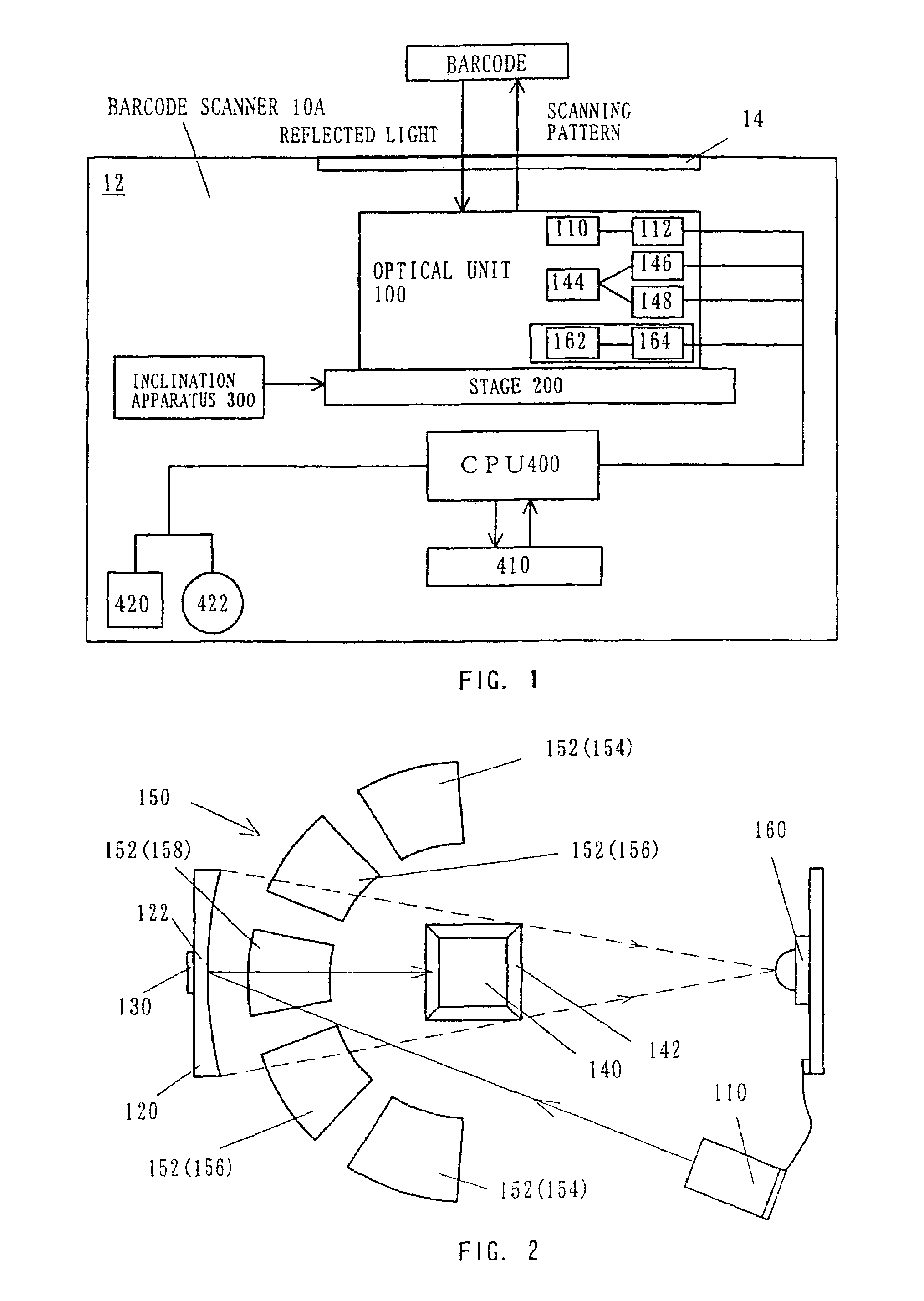
[0064]Referring to the accompanying drawings, a description will be given of barcode scanner 10A of a first embodiment according to the present invention. Hereinafter, the same elements are designated by the same reference numerals, and a description thereof will be omitted. In addition, in the following description, barcode scanner 10 generalizes barcode scanners 10A, 10B, etc.

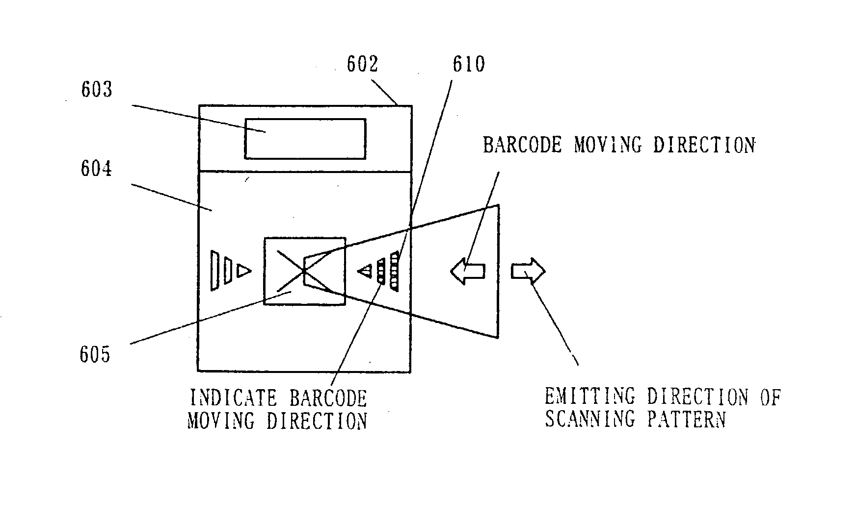
[0065]The barcode scanner 10A of the present invention, formed as a rectangular parallel shaped module (housing 12) emits a scanning pattern onto a barcode as a readable object through read window 14 in the housing 12, receives light reflected from the barcode, and reads the barcode data. The housing 12 may includes a plurality of read windows or is formed to be bendable, as seen in barcode scanner IDE which will be described later with reference to FIG. 30.

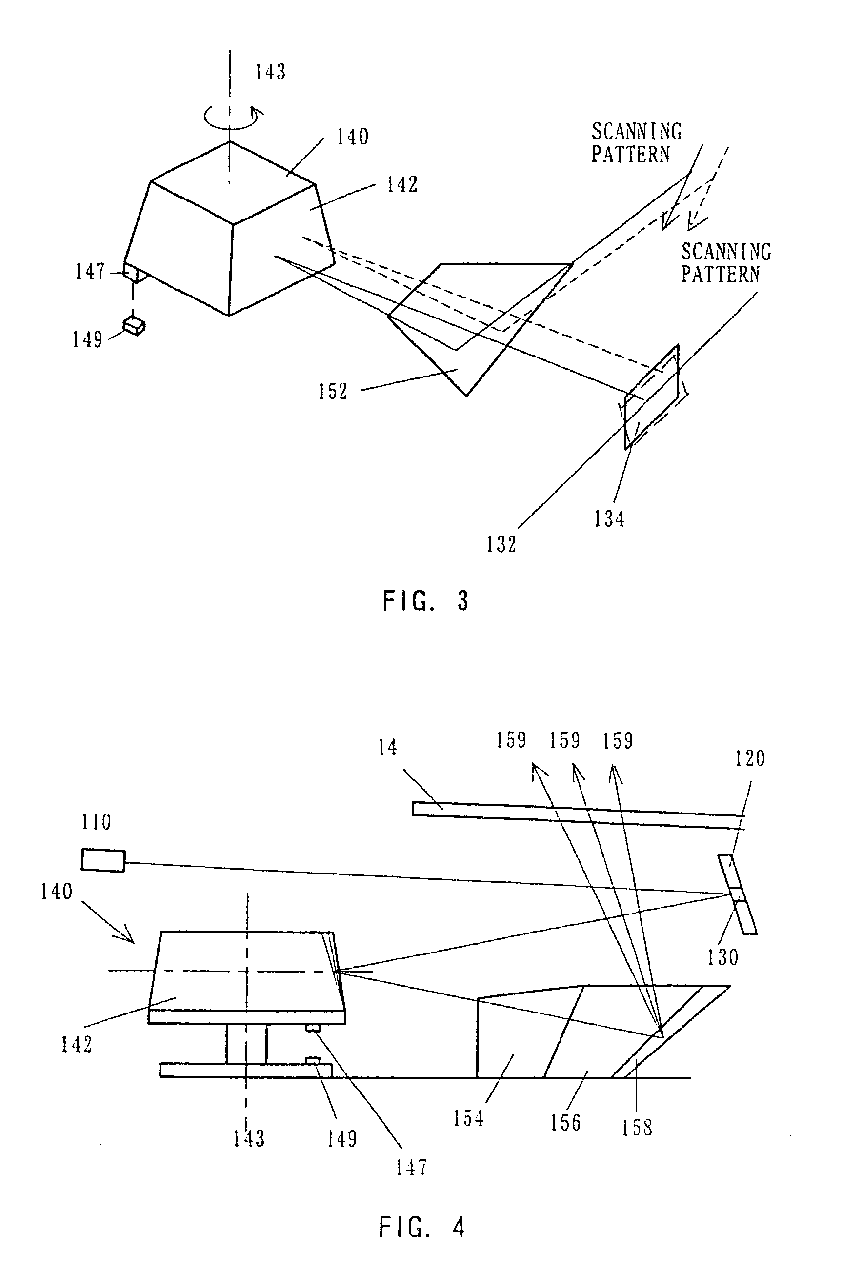
[0066]The barcode scanner 10A in FIG. 1 includes optical unit 100 which generates a scanning pattern, emits it in a predetermined direction, and receives ...


PUM


Abstract

An optical reader which is compatible with every environment irrespective of installation and usage environments, thereby enabling uniform manufacturing, satisfactory reading reliance, and operative safety and user-friendliness. The optical unit is mounted on the stage, and there is provided an inclination apparatus which inclines the stage at a desired angle. Thereby, without changing a preset optimal scanning pattern, only its emitting direction becomes changeable freely.

Description

[0001]This application is a division of prior application Ser. No. 09 / 970,781 filed Oct. 5, 2001, now U.S. Pat. No. 6,557,763, which is a division of prior grandparent application Ser. No. 09 / 657,065 filed Sept. 7, 2000, now U.S. Pat. No. 6,497,365, which is a division of prior great-grandparent application Ser. No. 09 / 253,943 filed Feb. 22, 1999, now U.S. Pat. No. 6,581,832.BACKGROUND OF THE INVENTION[0002]1. Field of the Invention[0003]The present invention relates generally to optical readers, and more particularly to an optical reader that changes a light scanning direction. The optical reader of the present invention is especially suitable for barcode scanners which optically read a barcode put on merchandises in POS systems and the like.[0004]2. Description of the Related Art[0005]Recently, barcode scanners have become more frequently used for cashiers in supermarkets, discount stores, home centers, etc. In general, operators who use a barcode scanner fixed onto a cashier tabl...

Claims


Application Information

Patent Timeline
Patent Type & Authority Patents(United States)
IPC IPC(8): G06K7/10G02B26/10
CPCG06K7/10613G06K7/1096G06K7/10861G06K7/10693G06K7/10
Inventor KATO, HIROAKIISHII, MITSUHARUAOKI, TOSHITAKA
Owner FUJITSU LTD
Why Eureka
Try Eureka