Centrifugal grinding mills

a centrifugal grinding mill and centrifugal technology, which is applied in the direction of grain treatment, etc., can solve the problems of high surface pressure at the internal surface of the centrifugal grinding machine, unsuitable for the production of very fine products, and incompatible with the structural or wear requirements of very fine discharge apertures. , to achieve the effect of reducing the length of the tubular passage, high flow rate capacity, and high inertial acceleration

Inactive Publication Date: 2006-07-04
F L SMIDTH & CO AS
View PDF12 Cites 42 Cited by
  • Summary
  • Abstract
  • Description
  • Claims
  • Application Information

AI Technical Summary

Benefits of technology

[0013]Generally the screening element includes a screening surface oriented substantially normal to the longitudinal axis of the grinding chamber wherein ground product is discharged from the chamber in a generally axial direction. This discharge from the grinding chamber in an axial direction requires that discharge occurs in a region adjacent the axis of symmetry of the chamber. This is a region associated with reduced impact pressures and corresponding reduced abrasive wear, compared with the periphery of the chamber in which discharge occurs in the prior art machine.
[0014]Preferably, the screening element includes a member having a perforated area disposed symmetrically about the axis of symmetry of the grinding chamber. More preferably, the screening element includes a planar member having a perforated plane area aligned normal to, and symmetrical with, the axis of symmetry of the grinding chamber. A consequence of this specific geometry of the perforated plane area, containing discharge openings, is that motion of grinding media and feed material is substantially parallel with the surface of the plane area. Hence contact pressures, and corresponding abrasive wear at the plane area surface, are relatively low.
[0017]Another feature of a preferred embodiment of the invention is that the fine product flows through the perforated area of the screening element, and discharges from an end of the grinding chamber remote from the point of nutation symmetry. Discharge of product from the grinding chamber in this embodiment is enhanced by the high inertial acceleration effect of the chamber motion. This ensures a relatively high flowrate capacity per unit of area of discharge openings.
[0018]A feature of another preferred embodiment of the invention is that the fine product flows through the perforated area of the screening element, and discharges from the grinding chamber through a tubular passage which passes through the feed opening adjacent the point of nutation symmetry. With this discharge configuration, flow of fine product is induced through the perforated area to a tubular flow passage, and out of the grinding chamber, by a pump device which provides a pressure gradient along the flow passage. In this embodiment, the axial location of the perforated area may vary typically from adjacent the plane containing the grinding chamber maximum internal diameter to a position approaching the entry of the feed passage to the chamber. The higher position of the perforated area in the grinding chamber has the advantage of requiring a reduced unsupported length of the tubular passage.
[0020]In another embodiment of the invention, rotation of the grinding chamber about its axis of symmetry is prevented by a torque-restraining device connecting the grinding chamber to the support member.

Problems solved by technology

It has been found from experience that centrifugal grinding machines having discharge openings of the type shown in FIGS. 1 and 2 are unsuited to production of very fine product.
Furthermore, the very high surface pressures at the internal surface of the grinding chamber is not compatible with the structural or wear requirements of very fine discharge apertures.

Method used


Image

  • Centrifugal grinding mills
  • Centrifugal grinding mills
  • Centrifugal grinding mills

Examples


Embodiment Construction

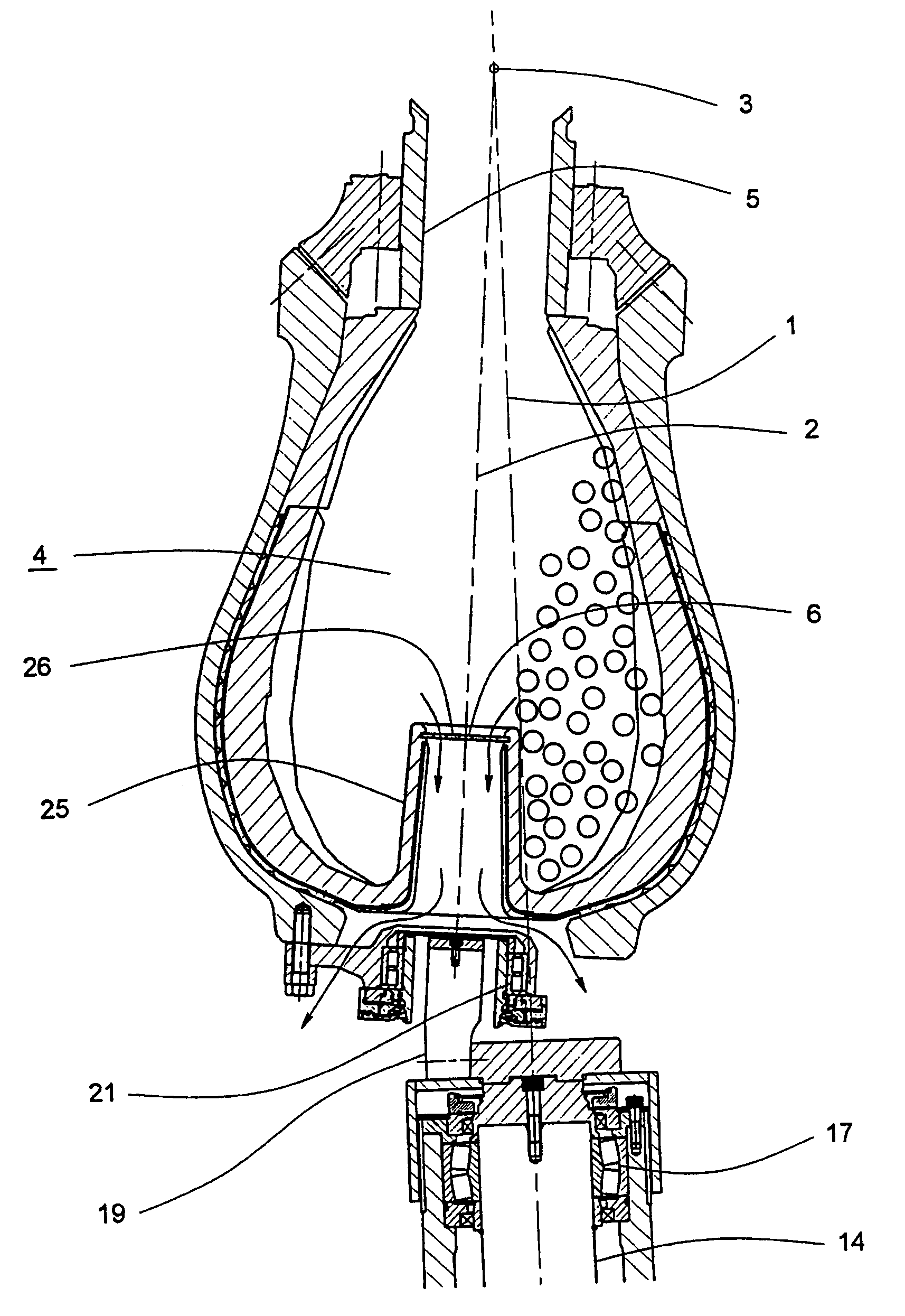
[0028]As best shown in FIGS. 3 to 5 there is one embodiment of a centrifugal grinding mill comprising:

[0029]a vertical axis of revolution 1, a nutating axis 2 intersecting axis 1 at a point of nutation symmetry 3,

[0030]a grinding chamber 4 symmetrical about axis 2 connecting with feed passage 5 at its upper end and having discharge openings 6 of a screening element 26 located within a plane area aligned normal to, symmetrical with, and intersected by the axis 2, and adjacent the plane containing the maximum diameter of the grinding chamber 4,

[0031]support means comprising a frame member or members 7 adapted to support the mill and transmit forces and moments generated by the mill to suitable foundations,

[0032]constraint means for determining the form of nutating motion of the grinding chamber comprising annular nutating bearing surfaces 8 and 9 rolling on corresponding fixed bearing surfaces 10 and 11 and nutating and fixed part spherical surfaces 12 and 13 respectively having centr...


PUM


Abstract

The present invention relates to a centrifugal grinding mill comprising a vertical axis of revolution (1), a nutating axis (2) intersecting axis (1) at a point of nutation symmetry (3), a grinding chamber (4) symmetrical about axis (2) connecting with feed passage (5) at its upper end and having discharge openings (6) of a screening element (26) located within a plane area aligned normal to, symmetrical with, and intersected by the axis (2), and adjacent the plane containing the maximum diameter of the grinding chamber (4).

Description

CROSS-REFERENCE TO RELATED APPLICATIONS[0001]This application is the National Stage of International Application No. PCT / AU00 / 01255, filed Oct. 16, 2000, which was published in English under PCT Article 21(2). This application also claims benefit of Australian Provisional Application No. PQ3555.FIELD OF THE INVENTION[0002]The present invention relates generally to centrifugal grinding mills and relates particularly, though not exclusively, to centrifugal grinding mills which perform the size reduction of solid particles by the action of loose grinding media which are driven with a gyrating and tumbling motion.BACKGROUND TO THE INVENTION[0003]Centrifugal grinding mills have been widely applied for the comminution of solid particles, in particular for the size reduction of mineral ores. A feature of centrifugal grinding mills is that the centrifugal acceleration imparted to the mill contents as a consequence of their gyrating motion has the effect of greatly enhancing the rate of comm...

Claims


Application Information

Patent Timeline
Patent Type & Authority Patents(United States)
IPC IPC(8): B02C18/18B02C2/04B02C17/14B02C17/18
CPCB02C17/1855B02C17/14
Inventor HOYER, DAVID IAN
Owner F L SMIDTH & CO AS
Why Eureka
Try Eureka