Track slot fastener

a technology of track fasteners and slots, applied in the field of fasteners, can solve the problems of difficult replacement, difficult installation and use of devices, and the limitation of conventional track fasteners,

Inactive Publication Date: 2006-07-04
NISSAN MOTOR CO LTD
View PDF134 Cites 95 Cited by
  • Summary
  • Abstract
  • Description
  • Claims
  • Application Information

AI Technical Summary

Benefits of technology

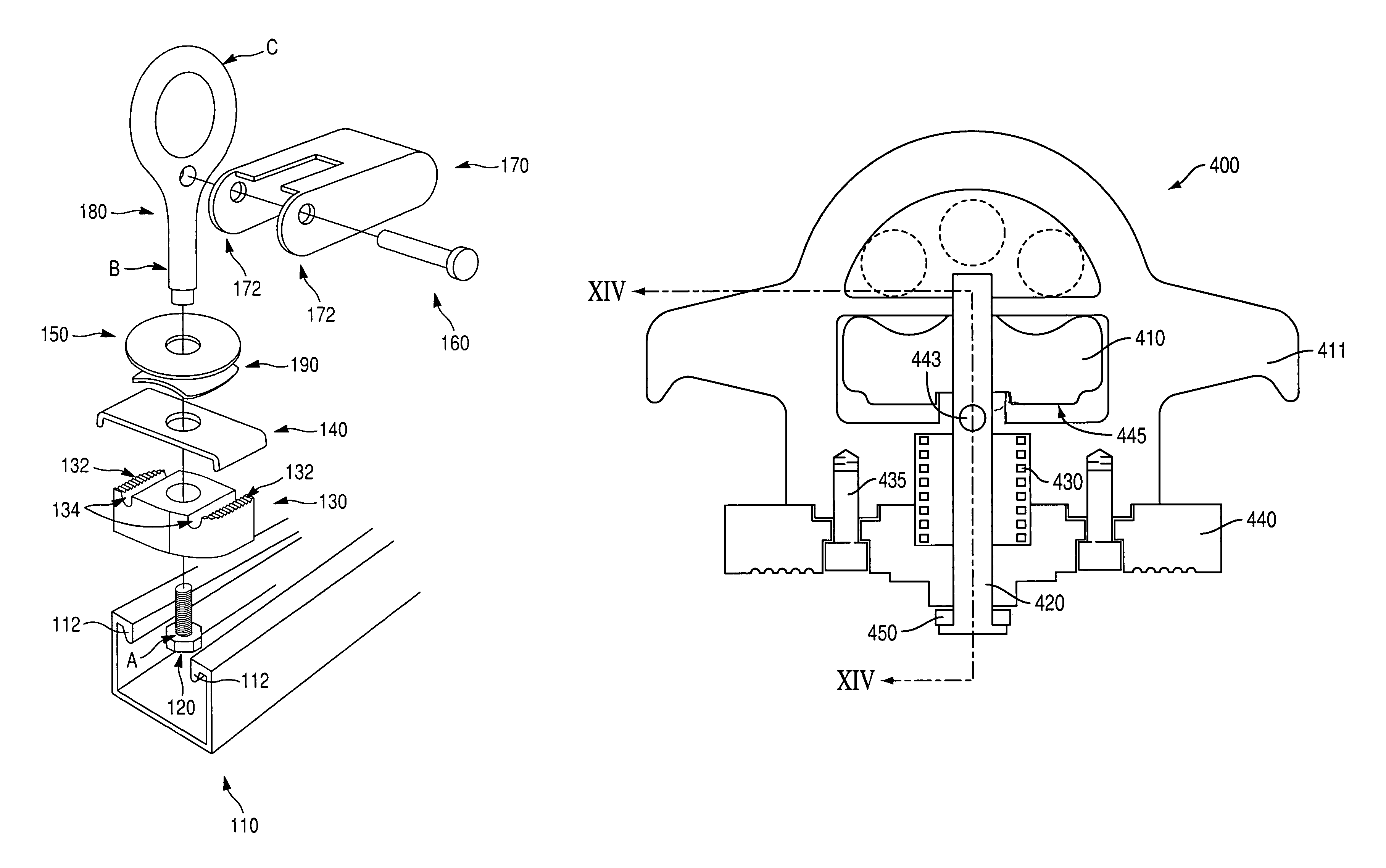
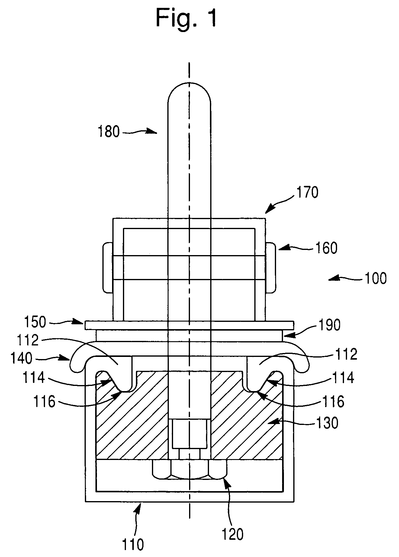
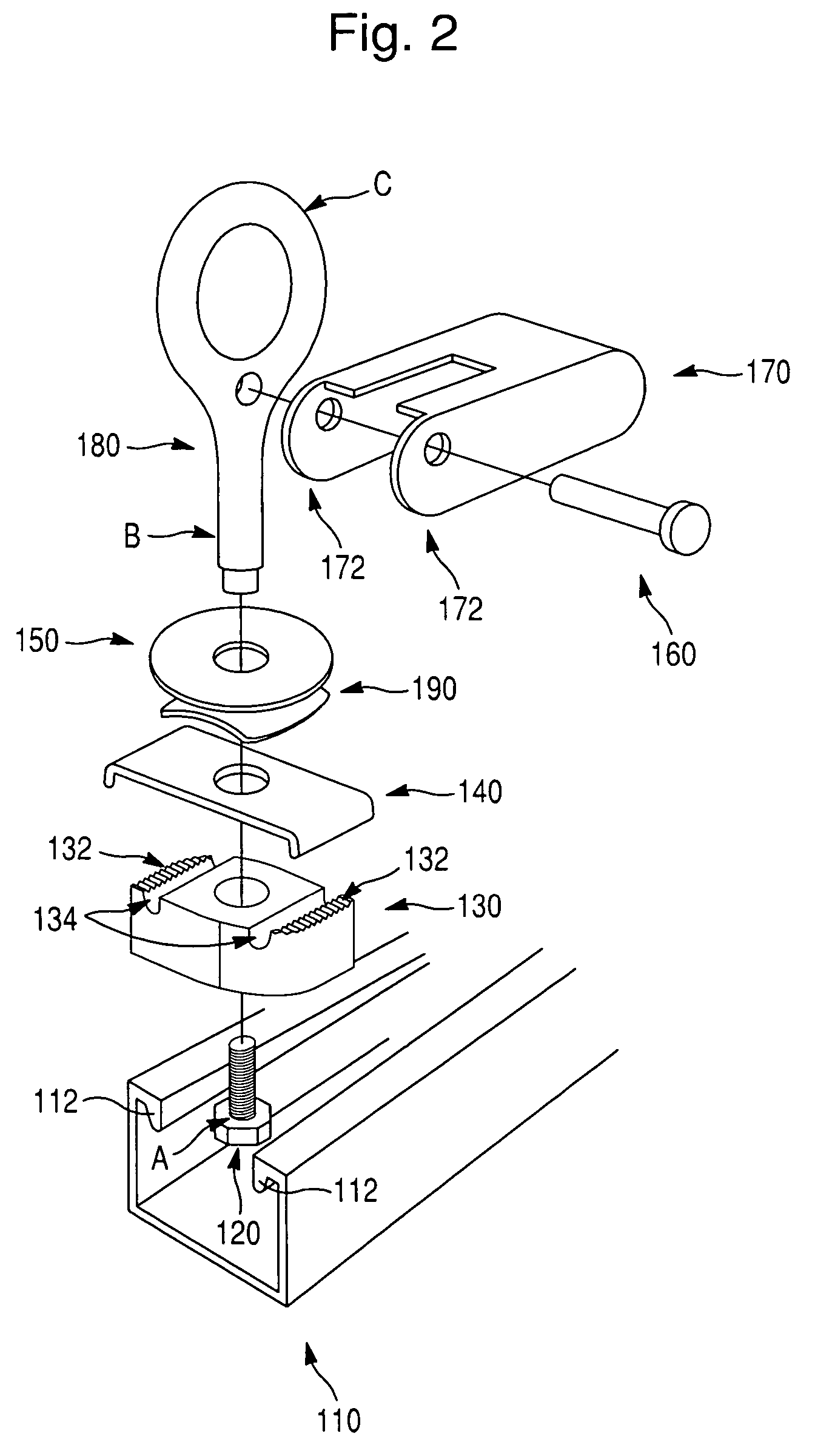
[0020]According to another embodiment of the present invention, a slidably retainable fastener assembly for securing loads to a track is provided, comprising a retainer adapted to fit at least partly within a track slot of the track, and a cam member operating on the retainer, the cam member being positionable in at least a first position and a second position. When the cam member is positioned in the first position, the cam member causes the retainer to disengage the track slot thereby allowing the fastener to be movable within the track slot, and when the cam member is positioned in the second position, the cam member causes the retainer to engage the track slot thereby causing the fastener to remain stationary within the track slot.

Problems solved by technology

These devices, however, can be difficult to install and use, which detracts from their desirability in consumer environments such as original equipment manufactured (OEM) vehicles (e.g., pickup trucks, mini-vans, sport-utility vehicles (SUV) etc.).
Often, conventional track fasteners can only be loaded from an end of the track slot (i.e., their design does not facilitate top down loading), and are thus difficult to replace if broken.
Also problematic, many of these fasteners have limited load capacities, such as fasteners available on roof racks, and are thus unsuitable for applications such as truck beds and cargo shipping where heavier loads are placed.
These devices, however, often require a user to have a wrench to loosen / tighten the bolt, which detracts from their ease of use.
These devices, however, are limited to the specific predetermined fastening locations, which reduces their utility for many applications.
Moreover, as with other conventional track fasteners, these devices typically require the car to be loaded into the track slot from one end of the track slot, making it substantially more difficult to repair or replace a given fastener.

Method used


Image

  • Track slot fastener
  • Track slot fastener
  • Track slot fastener

Examples


second embodiment

[0048]A fastener assembly retainable within a track slot according to another embodiment of the present invention is shown in FIG. 3, with parts thereof depicted in greater detail in FIGS. 4 and 5A–5G. The fastener assembly 200 according to this second embodiment comprises a cleat 210 including a base portion 220 adapted to fit within the track slot 110 (preferably in such a way as to provide for top-down loading). The cleat 210 is locked to the track slot 110 (i.e., in an engagement position) via ratchet lock 240. It should be appreciated that the cleat 210 refers to any slidable member adapted to fit within the track slot 110. It should also be appreciated that the term “ratchet” refers to a device that is tightened as it rotates until a predetermined amount of torque is attained, and then spins freely, re-releases, locks, or indicates in some manner that the required fastening torque has been attained.

[0049]Hence, the ratchet lock 240 is preferably configured to limit the maximum...

third embodiment

[0056]According to this third embodiment, the fastener assembly 300 includes a pin lock 305 operating on the retainer 330, the pin lock 305 being operable in a released / disengagement position (FIGS. 6, 8, 10, 12), and in a locked / engagement position (FIGS. 7, 11). The pin lock 305 includes a first pin 360 coupled to the retainer 330 via shaft 320 and linked to a second pin 370 via a first locking arm 390. A welded base portion 350 (e.g., a lockplate) or the like may be used to couple the shaft 320 to the retainer 330 depending on the particular implementation. The pin lock 305 further includes a third pin 380 coupled to the handle operating on the pin lock 305 and linked to the second pin 370 via a second locking arm 395. Second locking arm 395 is preferably an integral part of the handle 312 (FIGS. 10, 11) but is described as a separate arm for illustration purposes.

[0057]The operation of the pin lock 305 will now be described in reference to FIG. 9. For purposes of explanation, bo...


PUM


Abstract

A slidably retainable fastener assembly for securing loads to a track is provided with a retainer adapted to fit at least partly within a track slot and a member operating on the retainer, the member being positionable in at least a first position and a second position. When the member is positioned in the first position, the member causes the retainer to disengage the track slot thereby allowing the fastener to be movable within the track slot, and when the member is positioned in the second position, the member causes the retainer to engage the track slot thereby causing the fastener to remain stationary within the track slot.

Description

CORRESPONDING RELATED APPLICATIONS[0001]The present application is a divisional of U.S. application Ser. No. 10 / 336,033, filed on Jan. 2, 2003 and now U.S. Pat. No. 6,827,531. The present application is related to U.S. application Ser. No. 09 / 874,979, filed on Jun. 7, 2001 and now U.S. Pat. No. 6,846,140, and U.S. Pat. No. 6,712,568, issued on Mar. 30, 2004, to Mark D. Snyder et al., all of which are incorporated by reference herein in their entirety.BACKGROUND OF THE INVENTION[0002]1. Field of the Invention[0003]The present invention relates generally to fasteners for securing loads to a track, and more particularly, to adjustable fasteners for securing loads to a track mounted in or near a truck bed.[0004]2. Background of the Invention[0005]Fasteners for securing loads to framing, tracks, and channels have been commercially available for some time. Some conventional fasteners used in automotive track applications will be briefly described below.[0006]Conventional track fasteners h...

Claims


Application Information

Patent Timeline
Patent Type & Authority Patents(United States)
IPC IPC(8): B60P7/08B61D45/00
CPCB61D45/001B60P7/0815
Inventor WOMACK, DARRENBOWES, WILLIAM G.
Owner NISSAN MOTOR CO LTD
Why Eureka
Try Eureka