
Liquid crystal display device and method for fabricating the same

a technology of liquid crystal display and liquid crystal, which is applied in the direction of identification means, instruments, non-linear optics, etc., can solve problems such as rough display, and achieve the effect of wide viewing angle and bright high-quality display free from roughness

Inactive Publication Date: 2006-07-04
SHARP KK
View PDF13 Cites 4 Cited by
  • Summary
  • Abstract
  • Description
  • Claims
  • Application Information

AI Technical Summary

Benefits of technology

[0016]An object of the present invention is providing a liquid crystal display device that has a wide viewing angle characteristic and permits bright high-quality display free from roughness, and a method for fabricating such a liquid crystal display device.
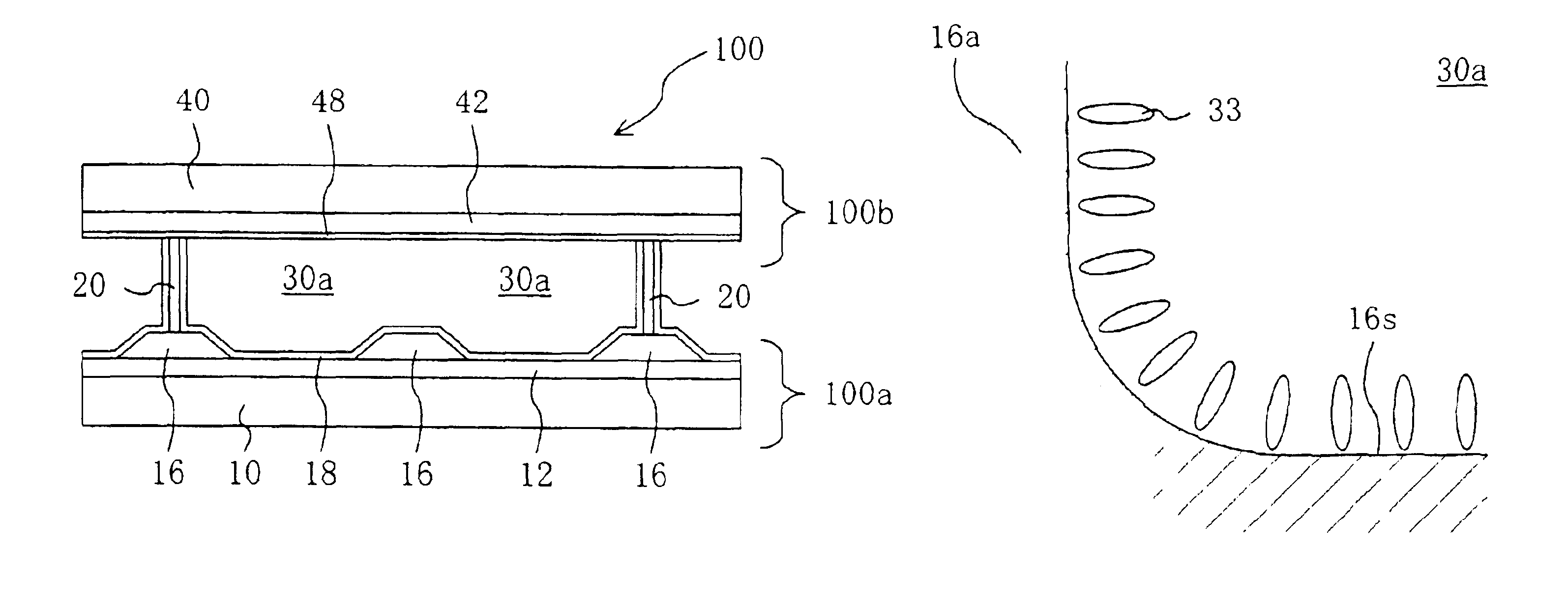
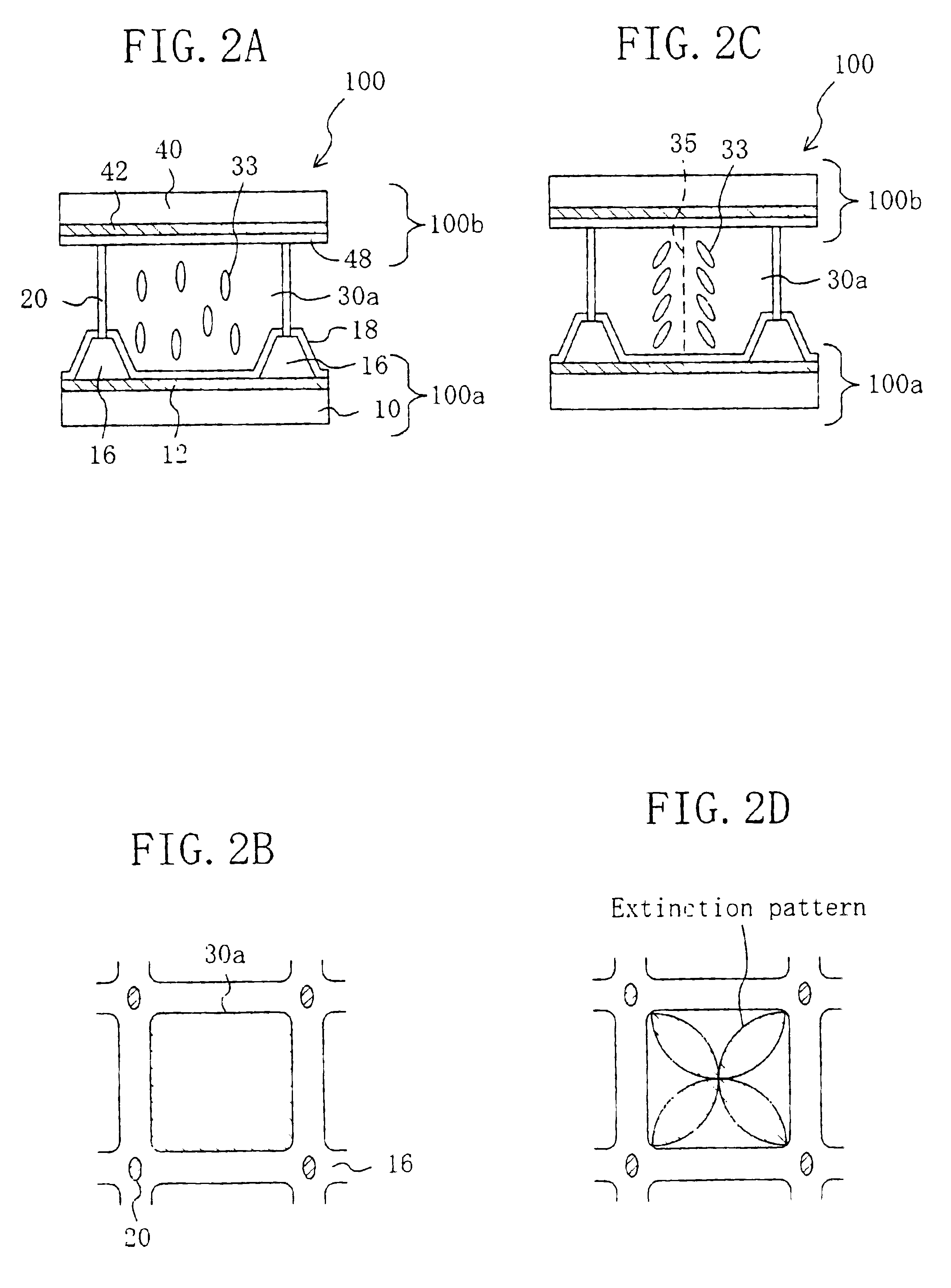
[0024]According to the present invention, in the ASM mode LCD, the corners of the polygonal liquid crystal regions substantially surrounded by the wall structures are dulled. Therefore, the alignment of the liquid crystal molecules changes continuously in the corners of the liquid crystal regions. This prevents occurrence of an alignment disturbance of the liquid crystal molecules, and thus minimizes the variation in the viewing angle characteristic of display and eliminates the necessity of shading the alignment disturbance with the black matrix. As a result, a liquid crystal display device having a wide viewing angle characteristic and providing bright, high-quality display free from roughness is obtained. The alignment of the liquid crystal molecules is further stabilized if the corners have a shape of a curve. The effect of stabilizing the alignment of the liquid crystal molecules is great if the liquid crystal molecules are aligned vertical to the side faces of the wall structures.
[0025]A negative photosensitive resin is used for the formation of the wall structures. By adopting this construction, a liquid crystal display device can be easily fabricated by changing the exposure amount in the light exposure step in the conventional process of forming the wall structures (polymer walls). More concretely, in the formation of the wall structures using a negative photosensitive resin, the negative photosensitive resin may be subjected to excessive light exposure via a mask having polygonal light-shading portions. By only this excessive light exposure, the corners of the regions substantially surrounded by the wall structures can be shaped into a curve.

Problems solved by technology

This may cause a variation in the viewing angle characteristic of the liquid crystal display device and result in rough display.

Method used


Image

  • Liquid crystal display device and method for fabricating the same
  • Liquid crystal display device and method for fabricating the same
  • Liquid crystal display device and method for fabricating the same

Examples


embodiment 1

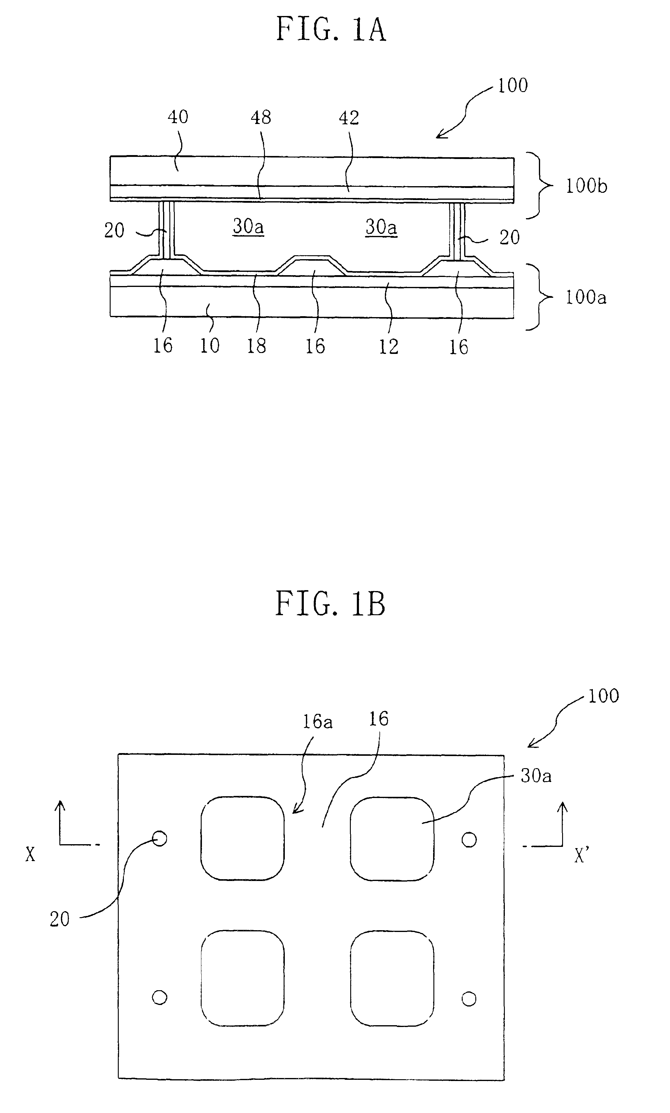
[0038]A liquid crystal display device (LCD) 100 of EMBODIMENT 1 of the present invention is schematically shown in FIGS. 1A and 1B: FIG. 1A is a cross-sectional view of the LCD 100 taken along line X-X′ of FIG. 1B which is a plan view thereof (viewed from the direction normal to the substrate plane). In EMBODIMENT 1, a construction using a liquid crystal material having negative dielectric anisotropy and a vertical alignment film is exemplified. It should however be noted that this embodiment is not limited to this construction.

[0039]The LCD 100 includes a first substrate 100a, a second substrate 100b, and a liquid crystal layer 30 sandwiched by the two substrates. The liquid crystal layer 30 includes liquid crystal molecules (not shown) having negative dielectric anisotropy. The first substrate 100a is constructed as follows. A first transparent electrode 12 made of ITO or the like is formed on the surface of a first transparent substrate made of glass or the like facing the liquid...


PUM


Abstract

The liquid crystal display device of the present invention includes: a first substrate; a second substrate; a liquid crystal layer sandwiched by the first and second substrates; and wall structures formed on a surface of the first substrate facing the liquid crystal layer for dividing the liquid crystal layer into a plurality of liquid crystal regions. Liquid crystal molecules in the plurality of liquid crystal regions are aligned axially symmetrically with respect to an axis vertical to a surface of the first substrate. The liquid crystal regions have a shape of a polygon having dulled corners. The alignment direction of the liquid crystal molecules in the liquid crystal regions with respect to side faces of the wall structures in the corners changes continuously.

Description

BACKGROUND OF THE INVENTION[0001]The present invention relates to a liquid crystal display device and a method for fabricating the same. More particularly, the present invention relates to a liquid crystal display device where liquid crystal molecules are aligned axially symmetrically in liquid crystal regions separated from one another by wall structures.[0002]Conventionally, twisted nematic (TN) and super-twisted nematic (STN) liquid crystal display devices (LCDS) are used as display devices utilizing the electrooptic effect. In order to widen the viewing angle of these LCDS, various techniques are now under vigorous development.[0003]As one of the viewing angle widening techniques proposed so far, Japanese Laid-Open Patent Publication No. 6-301015 and No. 7-120728 disclose a so-called axially symmetrically aligned microcell (ASM) mode LCD where liquid crystal molecules are aligned axially symmetrically in respective liquid crystal regions separated from one another by polymer wal...

Claims


Application Information

Patent Timeline
IPC IPC(8): G02F1/1339G02F1/1337G02F1/139G09F9/00G09F9/30
CPCG02F1/1337G02F1/1393G02F2001/133776G02F1/133776
Inventor KISHIMOTO, KATSUHIKO
Owner SHARP KK
Learn More