Direct digital access arrangement circuitry and method for connecting to phone lines
Inactive Publication Date: 2006-07-04
SILICON LAB INC
View PDF148 Cites 13 Cited by
Summary
Abstract
Description
Claims
Application Information
AI Technical Summary
This helps you quickly interpret patents by identifying the three key elements:
Problems solved by technology
Method used
Benefits of technology
[0014]The above-referenced deficiencies in the prior art are addressed by the present invention, which provides a reliable, inexpensive, lightweight isolation system that is substantially immune to noise
Problems solved by technology
However, analog signal communication through a transformer is subject to low frequency bandwidth limitations, as well as distortion caused by core non-lineanties.
Further disadvantages of transformers are their size, weight and cost.
However, two separate pulse transformers are disclosed for bidirectional communication with this technique, resulting in a cost disadvantage.
Another disadvantage of transformer coupling is that additional isolation elements, such as relays and opto-isolators, are typically required to transfer control signal information, such as phone ID line hook-stitch control and ring detect across the isolation barrier, further increasing the cost and size of transformer-based isolation solutions.
The disadvantage of this technique is that the analog communication, although differential, is not robust.
Mismatches in the differential components allow noise signals, which can capacitively couple into the isolation barrier, to easily corrupt both the amplitude and timing (or phase) of the analog modulated signal, resulting in unreliable communication across the barrier.
This scheme also requires separate isolation components for control signals, such as hook-switch control and ring detect, which increase the cost and complexity of the solution.
Furthermore, since capacitively coupled noise can cause timing (or phase) errors of voltage transitions in addition to amplitude errors.
These modulation schemes remain sensitive to noise interference at the isolation barrier.
Consequently one disadvanta
Method used
Image
Click on the blue label to locate the original text in one second.
Reading with bidirectional positioning of images and text.
Examples
Embodiment Construction
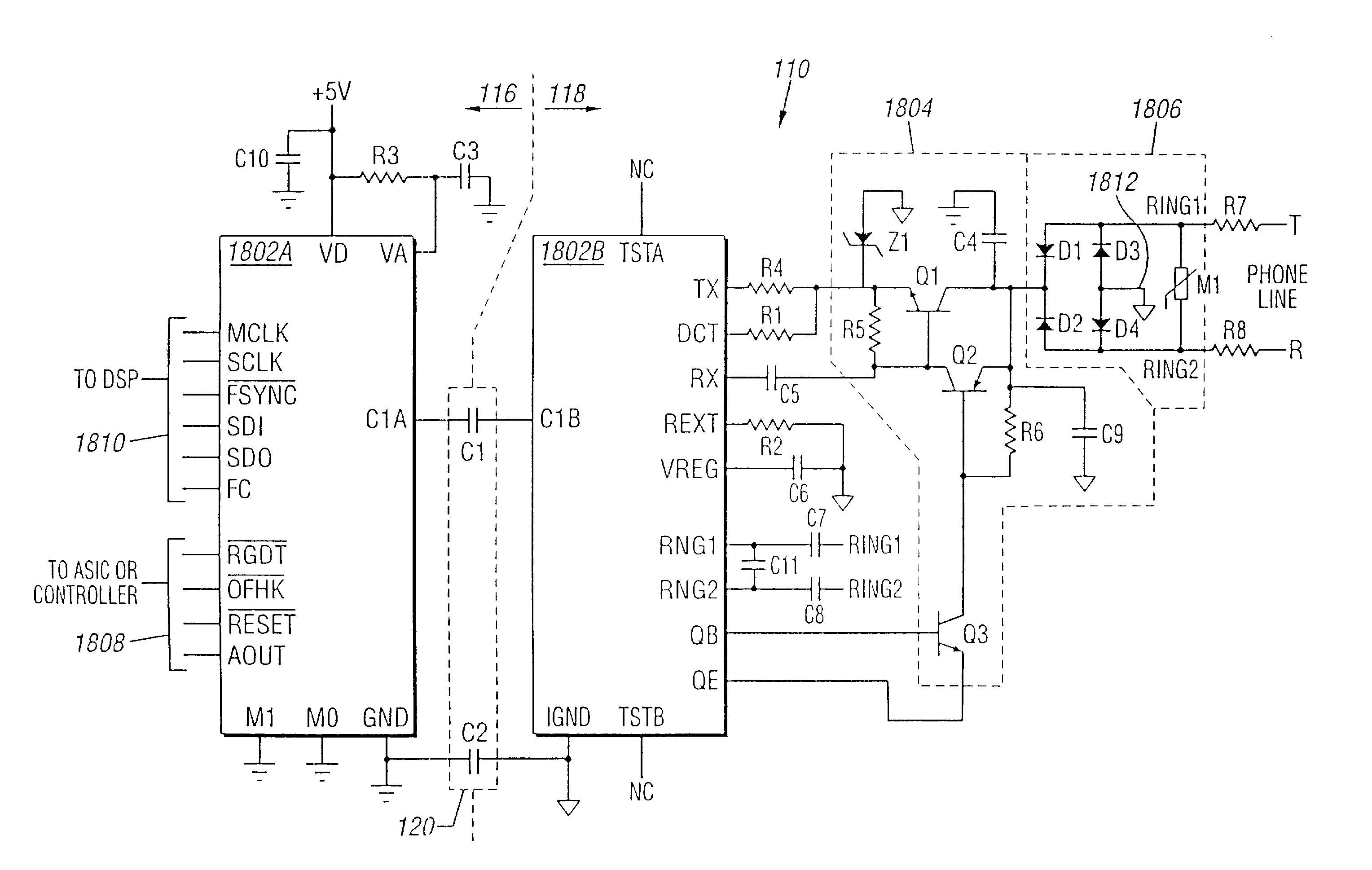
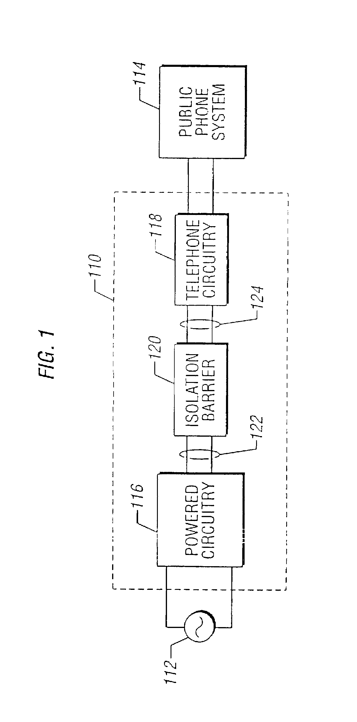
[0044]In order to provide a context for understanding this description, FIG. 1 illustrates a typical application for the present invention: a telephone that includes circuitry powered by a source external to the phone system. A basic telephone circuit 118 is powered by the “battery” voltage that is provided by the public telephone system and does not have a separate power connection. Many modern phones 110, however, include radio (cordless), speakerphone, or answering machine features that require an external source of power 112, typically obtained by plugging the phone (or a power supply transformer / rectifier) into a typical 110-volt residential wall outlet. In order to protect public phone system 114 (and to comply with governmental regulations), it is necessary to isolate “powered circuitry”116 that is externally powered from “isolated circuitry”118 that is connected to the phone lines, to prevent dangerous or destructive voltage or current levels from entering the phone system. ...
PUM
Abstract
An isolation system is provided that is suitable for use in telephony, medical instrumentation, industrial process control and other applications. Preferred embodiments of the invention comprise a capacitive isolation barrier across which a digital signal is communicated. The system provides a means of communication across the isolation barrier that is highly immune to amplitude and phase noise interference. Clock recovery circuitry may be employed on one side of the isolation barrier to extract timing information from the digital signal communicated across the barrier, and to filter the effects of phase noise introduced at the barrier. Delta-sigma converters may be disposed on both sides of the isolation barrier to convert signals between analog and digital domains. An isolated power supply may also be provided on the isolated side of the barrier, whereby direct current is generated in response to the digital data received across the isolation barrier. Finally, a bidirectional isolation system is provided whereby bidirectional communication of digital signals is accomplished using a single pair of isolation capacitors. In preferred embodiments, the digital data communicated across the barrier consists of digital delta-sigma data signals multiplexed in time with other digital control, signaling and framing information.
Description
[0001]This application is a continuation of U.S. Ser. No. 10 / 127,285 filed on Apr. 22, 2002, entitled “Direct Digital Access Arrangement Circuitry and Method for Connecting to Phone Lines” which is a continuation of U.S. Ser. No. 09 / 035,175 filed on Mar. 4, 1998 now U.S. Pat. No. 6,385,235, entitled “Direct Digital Access Arrangement Circuitry and Method for Connecting to Phone Lines” which is a continuation-in-part of U. S. Ser. Nos. 08 / 841,409, now U.S. Pat. No. 6,137,827, 08 / 837,702 now U.S. Pat. No. 5,870,046, and 08 / 837,714 now U.S. Pat. No. 6,430,229, all filed on Apr. 22, 1997. Further, the following U.S. patent applications filed concurrently herewith Ser. No. 09 / 034,621, entitled “Digital Isolation System With Low Power Mode” by George Tyson Tuttle et al; Ser. No. 09 / 034,456, entitled “Digital Isolation System With ADC Offset Calibration” by Andrew W. Krone et al.; Ser. No. 09 / 034,455, entitled “Ring-Detect Interface Circuitry and Method for a Communication System” by Timot...
Claims
Application Information
Patent Timeline
Application Date:The date an application was filed.
Publication Date:The date a patent or application was officially published.
First Publication Date:The earliest publication date of a patent with the same application number.
Issue Date:Publication date of the patent grant document.
PCT Entry Date:The Entry date of PCT National Phase.
Estimated Expiry Date:The statutory expiry date of a patent right according to the Patent Law, and it is the longest term of protection that the patent right can achieve without the termination of the patent right due to other reasons(Term extension factor has been taken into account ).
Invalid Date:Actual expiry date is based on effective date or publication date of legal transaction data of invalid patent.