
Bag slitting apparatus

a bag slitting and bag technology, applied in the field of bag slitting apparatus, can solve the problems of affecting the safety of users, and affecting the product in the bag, so as to maintain the cleanliness of the room, support convenience, efficiency, and safety, and eliminate inadvertent mishaps.

Inactive Publication Date: 2006-07-11
SPELLBOUND DEVMENT GROUP
View PDF20 Cites 39 Cited by
  • Summary
  • Abstract
  • Description
  • Claims
  • Application Information

AI Technical Summary

Benefits of technology

[0010]The apparatus is meant to be disposable once the blade tip becomes dull to thereby eliminate inadvertent mishaps such as those which can occur with a conventional utility knife while changing a blade. Depending upon use-environment, the apparatus can be fabricated of autoclavable material to thereby maintain clean-room conditions. Additionally, apparatus construction preferably provides smooth transitions of all surface structures to thereby inhibit contamination and resulting potential cross-contamination during subsequent use. As is apparent, the bag slitting apparatus here defined provides operational utility while supporting convenience, efficiency, and safety in retrieving packaged products.

Problems solved by technology

While such sealed bags are highly efficient in maintaining product integrity, access into the interior of a bag for retrieval of a packaged product therein housed many times is not convenient.
In particular, a user may need to hand-tear a hole into the bag, or juggle the bag and its housed product while attempting to awkwardly use a cumbersome scissors, utility knife, razor blade, or the like to cut an opening through the bag wall.
Not only are such approaches possibly hazardous to the user, they also can be damaging to the product housed in the bag.

Method used


Image

  • Bag slitting apparatus
  • Bag slitting apparatus

Examples


Embodiment Construction

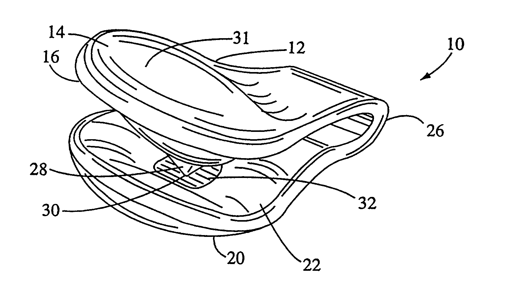
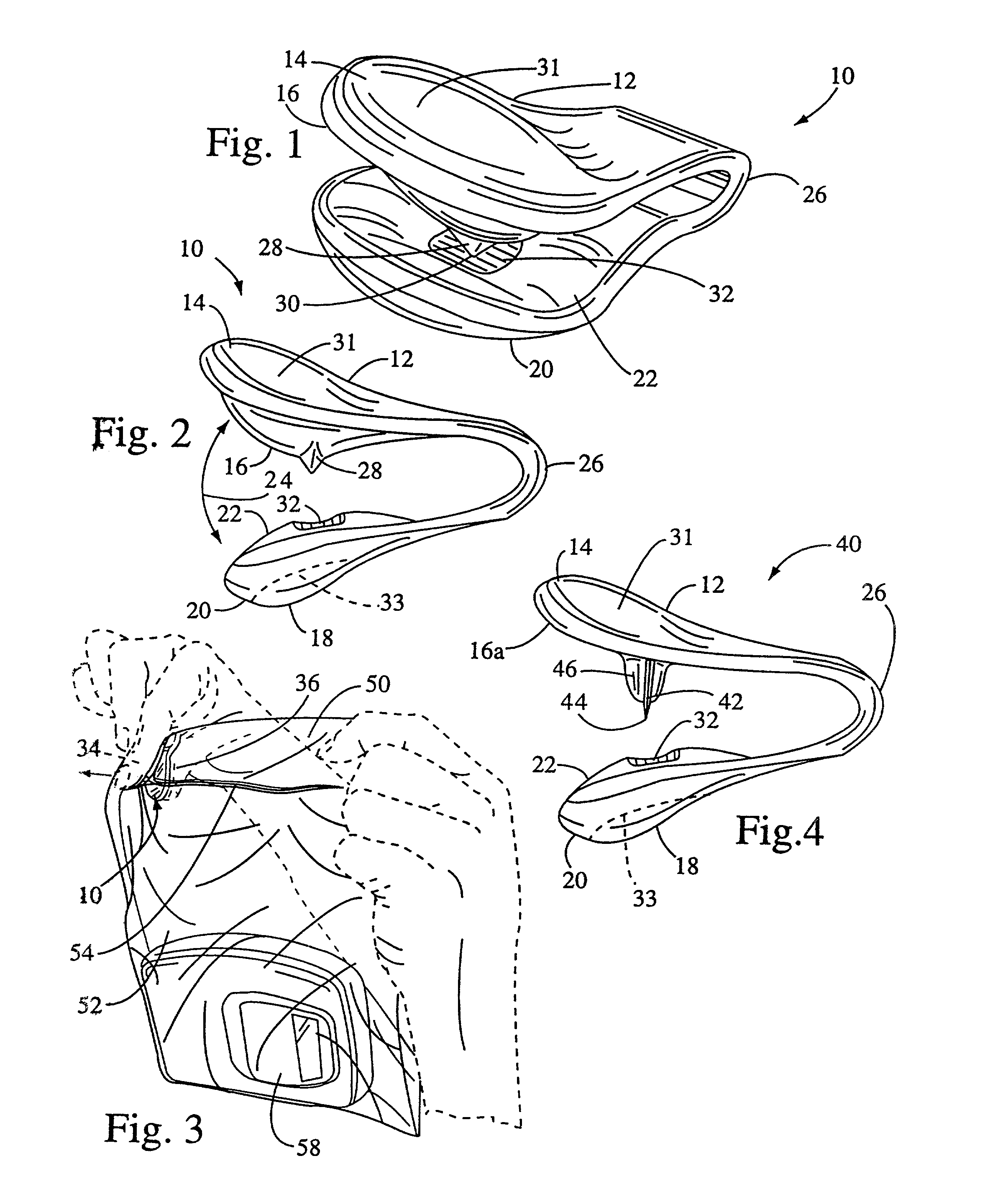
[0016]Throughout all of the drawing figures, like elements are identically numbered. Referring first to FIGS. 1 and 2, a bag slitting apparatus 10 for opening a sealed bag along an edge thereof is shown. The apparatus 10 has a first arm 12 having a first outer surface 14 and a first inner surface 16, and a second arm 18 having a second outer surface 20 and a second inner surface 22. The first and second arms 12, 18 are in tensioned movable opposed relationship to each other such that the first and second inner surfaces 16, 22 are movably positionable against each other as indicated by the arrow 24 of FIG. 2. Such tensioned relationship is conventionally attained by kinetically stressing the bridge 26 joining the arms 12, 18 as known in the art. The first and second arms 12, 18 are each significantly wider than the bridge 26, and the entirety of the first and second arms 12, 18 extend concavely from the bridge 26. One of the inner surfaces, here shown as the first inner surface 16, i...


PUM


Abstract

A bag slitting apparatus for opening a sealed bag along an edge of the bag. The apparatus has a first arm having first outer and inner surfaces, and a second arm having second outer and inner surfaces. The arms are in tensioned movable opposed relationship to each other such that the first and second inner surfaces are movably positionable against each other. One of these inner surfaces is a bladed inner surface having projecting therefrom a bag cutting blade with a distal blade tip, while the other inner surface has a blade tip receiver. Exteriorly, the first and second outer surfaces are concavedly contoured for simultaneous opposingly-squeezing receipt of a finger and thumb of a user. Placing the edge of the bag between the blade tip and blade tip receiver, squeezing the arms together such that the blade tip pierces the bag and travels to the tip receiver, and thereafter sliding the apparatus along the length of the bag edge produces a slit in the bag through which contents can be retrieved.

Description

CROSS-REFERENCE TO RELATED APPLICATIONS[0001]This is a continuation of application Ser. No. 09 / 607,477, filed Jun. 30, 2000, now abandoned.STATEMENT RE: FEDERALLY SPONSORED RESEARCH / DEVELOPMENT[0002](Not Applicable)BACKGROUND OF THE INVENTION[0003]The present invention relates in general to bag slitting apparatus for opening a sealed bag, and in particular to a bag slitting apparatus for opening a sealed bag along an edge thereof and generally constructed as a spring-tensioned, opposing arm device wherein the inner surface of one arm thereof has a projecting blade for slitting a bag placed between the arms and wherein the outer surfaces of the arms are concavedly contoured for simultaneous opposing receipt of a finger and thumb of a user.[0004]Employment of sealed, usually transparent, plastic bags for housing various products is a well-accepted packaging approach for maintaining such commodities in a ready-to-use condition. Typical products include those produced in food, medical, ...

Claims


Application Information

Patent Timeline
IPC IPC(8): B67B7/00B26B3/00B26B27/00
CPCB26B27/00
Inventor VOTOLATO, EARL J.
Owner SPELLBOUND DEVMENT GROUP
Learn More