Impact-absorbing end caps for levels

a level and end cap technology, applied in the field of level, can solve the problems of many levels having a greater length, easy damage to the level's body during use, and falling to the ground, so as to prevent damage to the level, reduce densities, and improve the effect of compression

Active Publication Date: 2006-07-11
MILWAUKEE ELECTRIC TOOL CORP
View PDF30 Cites 35 Cited by
  • Summary
  • Abstract
  • Description
  • Claims
  • Application Information

AI Technical Summary

Benefits of technology

[0008]Another object of the invention is to provide a level which allows for compression of its end caps when impacted.
[0011]Yet another object of the invention is to provide a level having increase impact-resistance with little additional weight.
[0015]In certain embodiments, the impact-absorbing level comprises a body including a level face for measuring a surface, the body extending from a first end to a second end; at least one vial mounted in the body at a predetermined angular relationship to the level face; and a first end cap fixed with respect to the first end, the first end cap comprising an outer layer and an intermediate layer, the intermediate layer fixed to the outer layer and having lower density than the outer layer, the intermediate layer positioned between the outer layer and the body. In such a level, the first end cap absorbs impacts to the outer layer to prevent damage to the body.
[0016]The level may further includes a second end cap fixed with respect to the second end, the second end cap comprising an second outer layer and a second intermediate layer, the second intermediate layer fixed to the second outer layer and having lower density than the second outer layer, the second intermediate layer positioned between the second outer layer and the body. The second end cap absorbs impacts to the second outer layer to prevent damage to the body.
[0021]The invention can also be considered an improvement upon a level including (a) a body extending from a first end to a second end, (b) a level face connected with respect to the body, the level face for measuring a surface, and (c) a vial mounted with respect to the body at a predetermined angular relationship to the level face. Such improvement includes a first dual-density end cap mounted to the first end and a second dual-density end cap mounted to the second end, the end caps having an outer layer and an intermediate layer, whereby impacts to an end cap result in compression of the end cap and dissipation of the impact to prevent damage to the level.
[0022]In such an improvement, the intermediate layers preferably have lower densities than the outer layers and are compressed more easily than the outer layers. The outer layers may be acrylonitrile butadiene styrene and the intermediate layers may be thermoplastic rubber though other materials may be used to accomplish the impact-absorption function while providing for sufficient bonding between one another and to the body of the level. The end caps may further comprise inner layers connecting the intermediate layers to the body. The intermediate layers preferably have lower densities than both the inner and outer layers and are compressed more easily than both the inner and outer layers. It is preferred that the inner layers be acrylonitrile butadiene styrene.

Problems solved by technology

A problem with such levels is that the vials and, to a lesser extent, the level's body can be damage easily during use.
Levels are often left in position on a surface to be measured or set and can be knocked off causing them to fall to the ground.
In addition, many levels have a greater length, frequently about four feet, and may be bumped or knocked by those who are more accustomed to dealing with tools of smaller dimensions.
In addition, the great length of some levels causes an increase in weight which can add to stresses involved with falling or being bumped.

Method used


Image

  • Impact-absorbing end caps for levels
  • Impact-absorbing end caps for levels
  • Impact-absorbing end caps for levels

Examples


Embodiment Construction

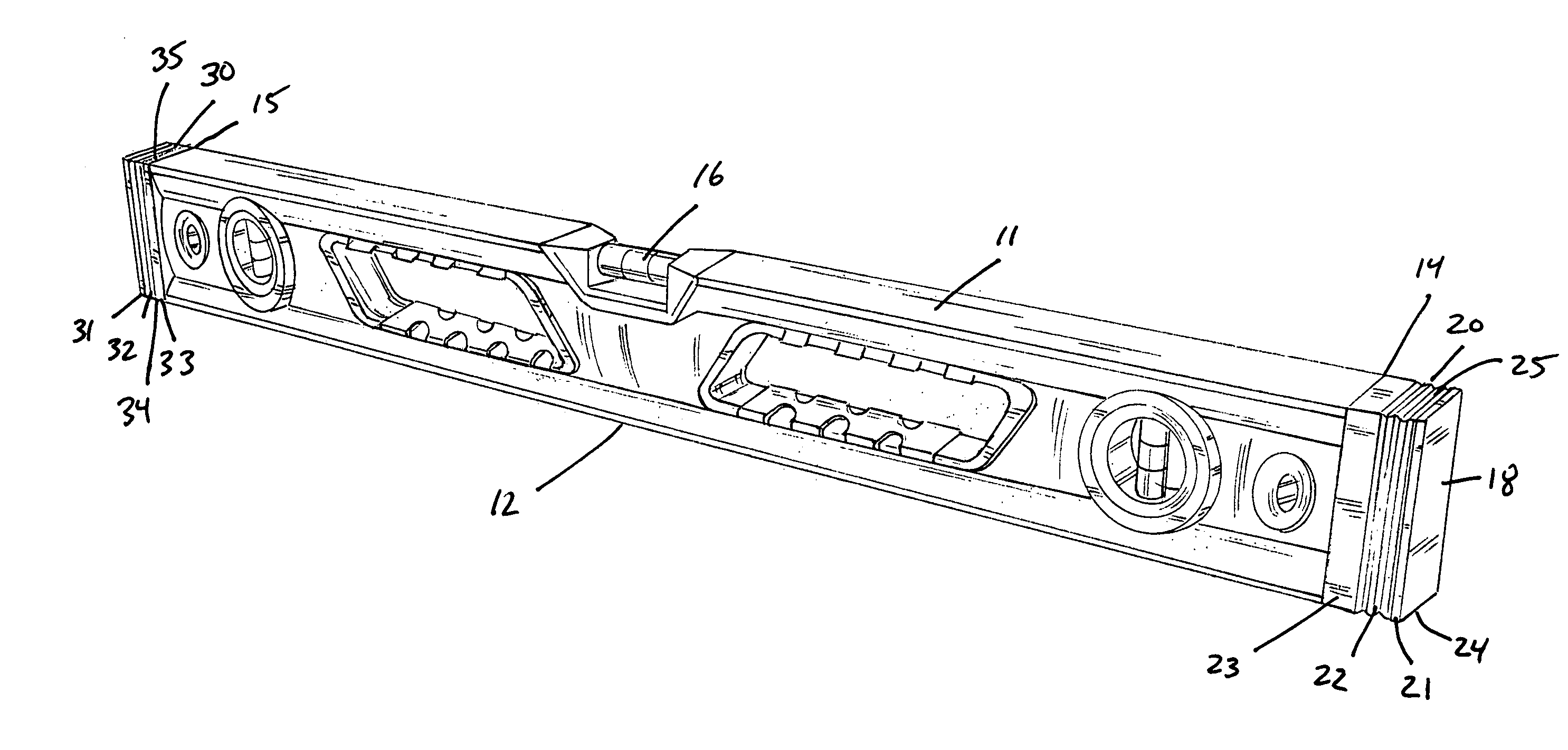
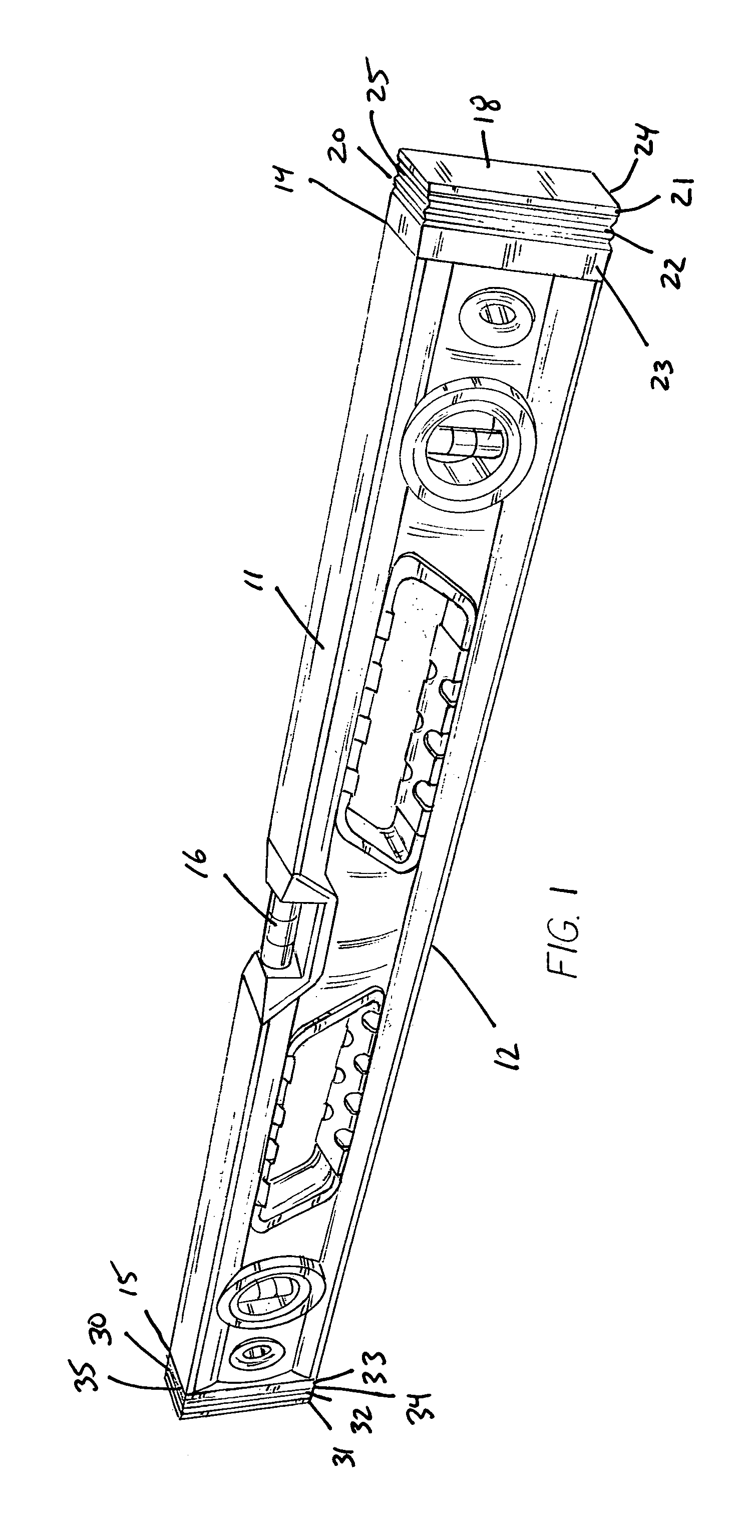
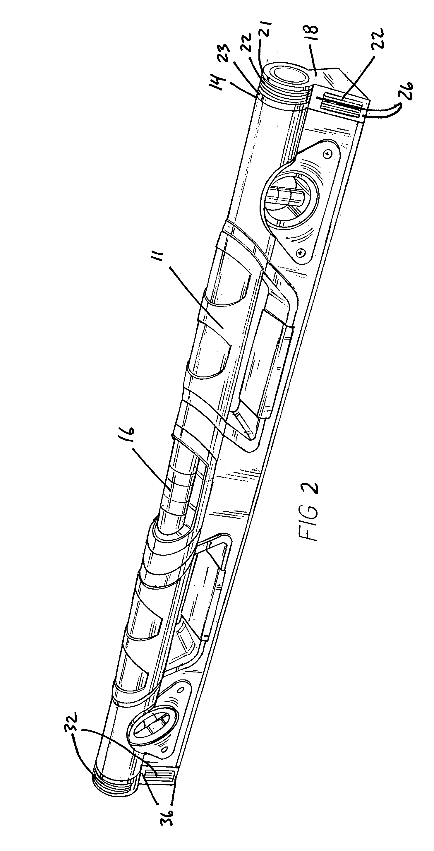
[0033]FIGS. 1 and 2 are perspective views of alternate levels 10 having impact-absorbing end caps 20,30. Each level 10 includes a body 11 having a level face 12 for measuring a surface 13 (see FIG. 3), the body extending from a first end 14 to a second end 15. Each level 10 further includes at least one vial 16 mounted in body 11 at a predetermined angular relationship to level face 12, such as parallel to, perpendicular to, or at another specific angle to level face 12.

[0034]First dual-density end cap 20 is fixed with respect to first end 14 and comprises an outer layer 21, an intermediate layer 22, and an inner layer 23. Outer layer 21 is fixed or bonded to intermediate layer 22 which is fixed or bonded to inner layer 23. Intermediate layer 22 has a lower density than outer layer 21 and inner layer 23 such that intermediate layer is compressed more easily and to a greater degree during impacts. Outer and inner layers 21,23 are preferably acrylonitrile butadiene styrene and interme...


PUM


Abstract

An impact-absorbing level is disclosed. The level comprises a body including a level face for measuring a surface, a vial mounted in the body at a predetermined angular relationship to the level face, and a first end cap fixed with respect to the first end, the first end cap comprising an outer layer and an intermediate layer, the intermediate layer fixed to the outer layer and having lower density than the outer layer, the intermediate layer positioned between the outer layer and the body, such that the first end cap absorbs impacts to the outer layer to prevent damage to the body. Also disclosed is a method of providing impact-absorption to a level in which a dual-density end cap is adhered to each end of the level.

Description

FIELD OF THE INVENTION[0001]This invention relates to geometric instruments and, more particularly, to levels (sometimes referred to as “spirit levels” used by carpenters and the like.BACKGROUND OF THE INVENTION[0002]Levels are used by carpenters, masons, drywallers and the like for helping to assure that surfaces are horizontal, vertical, or at a specified angular relationship to the horizon. A typical level includes at least two vials, one each for ascertaining whether a surface is “level,” i.e., horizontal, or “plumb,” i.e., vertical.[0003]A level comprises a measuring surface or surfaces and a vial set at an angular relationship to such surface(s). The vial is partially filled with a liquid such as mineral spirits. The vial is not completely filled and a bubble is thereby formed when the vial is closed. Typically, two marker rings are applied to the outside of the vial in positions to visually divide the cavity into three portions of about equal length. Level and plumb condition...

Claims


Application Information

Patent Timeline
Patent Type & Authority Patents(United States)
IPC IPC(8): G01C9/10G01C9/24B43L7/00G01C9/00G01C9/28
CPCG01C9/28
Inventor KIM, CHARLES D.
Owner MILWAUKEE ELECTRIC TOOL CORP
Why Eureka
Try Eureka