Coriolis mass flowmeter

a mass flowmeter and coriolis technology, applied in the field of coriolis mass flowmeters, can solve the problems of frequent recalibration and unsatisfactory attainable measuring accuracy, and achieve the effect of high degree of measuring accuracy

Inactive Publication Date: 2006-07-11
KRONE GMBH
View PDF5 Cites 72 Cited by
  • Summary
  • Abstract
  • Description
  • Claims
  • Application Information

AI Technical Summary

Benefits of technology

[0006]It is therefore the objective of this invention to introduce a Coriolis mass flowmeter that offers a high degree of measuring accuracy.
[0009]Even with the earlier Coriolis mass flowmeters designed as described above, a substantially improved measuring accuracy is obtainable especially in stimulating vibrations of the measuring tube circumference. Additionally, another preferred embodiment of the invention employs a second oscillator and a third oscillator, with the second oscillator positioned opposite the first oscillation sensor and the third oscillator opposite the second oscillation sensor, in each case at the same longitudinal distance on the measuring tube. Moreover, according to a preferred embodiment of the invention, the size of the second oscillator essentially corresponds to the size of the first oscillator and the size of the third oscillator essentially corresponds to the size of the second oscillation sensor, which again produces a “balanced” measuring tube.
[0010]Based on the Coriolis mass flowmeter concept described further above, the aforementioned objective is also achieved by providing a second oscillator and a third oscillator but not a third oscillation sensor, with the second oscillator positioned opposite the first oscillation sensor and the third oscillator opposite the second oscillation sensor, in each case at the same longitudinal distance on the measuring tube. Even without a third oscillation sensor, providing a second oscillator and a third oscillator can offer advantages in that it is possible to stimulate vibrations of the measuring tube that permit the real-time determination of characteristic properties of the Coriolis mass flowmeter such as its zero point and its sensitivity, a technique that has been described in DE 100 02 635 A1.
[0012]Although it says further above that a second oscillator and a third oscillator can be provided without also adding a third oscillation sensor, it is particularly desirable to simultaneously provide a second oscillator, a third oscillator and a third oscillation sensor, respectively positioned opposite the first oscillation sensor, the first oscillator and the second oscillation sensor, each being of the same size as the respectively opposite oscillation sensor or oscillator. A Coriolis mass flowmeter thus configured offers significant additional functionalities that can substantially enhance the measuring accuracy and reproducibility, while at the same time producing a “balanced” measuring tube.
[0016]In the preferred embodiments of the invention, the measuring tube features at both ends a coupling sleeve for connecting the measuring tube to a pipeline system, with the sleeves designed to permit a “soft” coupling of the measuring tube to the pipeline. Specifically, such “soft” coupling of the measuring tube to the pipeline is achieved in that the sleeves are in the form of bellows. This largely eliminates any transfer of vibrations from the measuring tube of the Coriolis mass flowmeter into the pipeline system with a potentially resulting retroreflection of spurious oscillations into the measuring tube. Moreover, it will be helpful for the decoupling of the measuring tube of the Coriolis mass flowmeter from the pipeline system when, according to a preferred configuration of the invention, both extremities of the measuring tube are provided with a terminal mass which terminal mass preferably extends around the perimeter, specifically in annular form, of the measuring tube.

Problems solved by technology

The problem with these prior-art Coriolis mass flowmeters, however, is their unsatisfactory attainable measuring accuracy which, in particular, requires frequent recalibration.

Method used


Image

  • Coriolis mass flowmeter
  • Coriolis mass flowmeter

Examples


Embodiment Construction

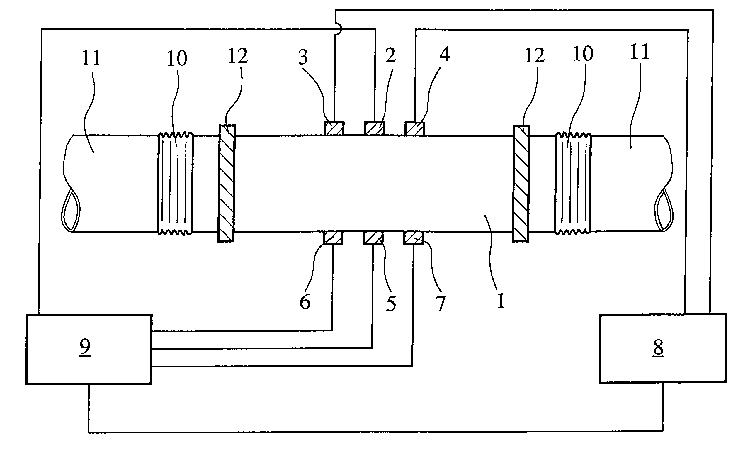
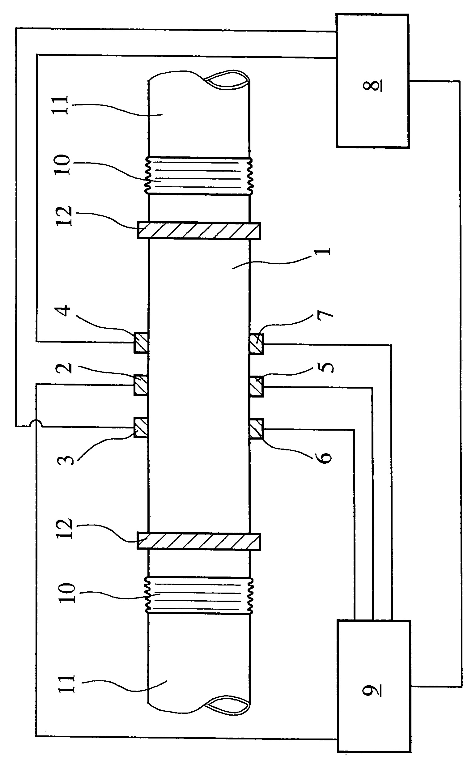
[0019]The Coriolis mass flowmeter schematically illustrated in the FIGURE incorporates a measuring tube 1 through which, when in operation, flows a fluid medium, not shown. The oscillation of the measuring tube 1 is activated by means of a first oscillator 2 which, viewed in the longitudinal direction of the measuring tube 1, is mounted precisely in the center of the measuring tube 1. In the longitudinal direction of the measuring tube 1, a first oscillation sensor 3 and a second oscillation sensor 4 are offset relative to the first oscillator 2. The first oscillation sensor 3 and the second oscillation sensor 4 are equidistant from the first oscillator 2. The first oscillator 2, the first oscillation sensor 3 and the second oscillation sensor 4 are all positioned along a line that extends parallel to the longitudinal axis of the measuring tube 1.

[0020]Located at a 180° angle opposite the first oscillator 2, the first oscillation sensor 3 and the second oscillation sensor 4, at the ...


PUM


Abstract

A Coriolis mass flowmeter incorporates a measuring tube for guiding a flowing medium, a first oscillator for the oscillatory stimulation of the measuring tube, as well as a first oscillation sensor and a second oscillation sensor for picking up Coriolis oscillations of the measuring tube. The first oscillator, the first oscillation sensor and the second oscillation sensor are mutually spaced apart in the longitudinal direction of the measuring tube and the first oscillator is activated by an oscillation-stimulating control device. A third oscillation sensor is provided and positioned opposite the first oscillator at the same longitudinal distance of the measuring tube. Additionally or alternatively, a second oscillator and a third oscillator may be provided, with the second oscillator positioned opposite the first oscillation sensor and the third oscillator positioned opposite the second oscillation sensor, in each case at the same longitudinal distance on the measuring tube. All mutually opposite oscillators and oscillation sensors are of the same size, resulting in a “balanced” measuring tube while opening up various possibilities for improving the evaluation and control of the flowmeter, which in turn provides greater reproducibility and measuring accuracy.

Description

BACKGROUND OF THE INVENTION[0001]1. Field of the Invention[0002]This invention relates to a Coriolis mass flowmeter incorporating a measuring tube for guiding a flowing medium, a first oscillator for vibrating the measuring tube, as well as a first oscillation sensor and a second oscillation sensor for capturing the vibrations of the measuring tube, in which configuration the first oscillator, the first oscillation sensor and the second oscillation sensor are mutually spaced apart in the longitudinal direction of the measuring tube and the first oscillator is activated by an oscillation-stimulating control device.[0003]2. Description of the Prior Art[0004]A Coriolis mass flowmeter of this type has been described in WO 95 / 16897 A2. The Coriolis mass flowmeter according to that document employs the concept of oscillatory stimulation of the circumference of the measuring tube, producing vibrations that cause the diameter of the measuring tube to undergo vibration-induced geometric vari...

Claims


Application Information

Patent Timeline
Patent Type & Authority Patents(United States)
IPC IPC(8): G01F1/84
CPCG01F1/8413G01F15/185G01F1/849G01F1/8418
Inventor HUSSAIN, YOUSSIF A.ROLPH, CHRIS N.HARRISSON, NEIL
Owner KRONE GMBH
Why Eureka
Try Eureka