Exhaust emission control apparatus and method for internal combustion engine

a technology of exhaust emission control and internal combustion engine, which is applied in mechanical equipment, electric control, machines/engines, etc., can solve the problems of deteriorating combustion stability and insufficient evaporation of fuel, and achieve the effect of effectively accelerating the early activation of the exhaust purifying catalyst and setting the ignition timing rang

Inactive Publication Date: 2006-07-11
NISSAN MOTOR CO LTD
View PDF10 Cites 51 Cited by
  • Summary
  • Abstract
  • Description
  • Claims
  • Application Information

AI Technical Summary

Benefits of technology

[0004]However, in this previously proposed direct-injection and spark-ignition type internal combustion engine; the fuel injection valve is located at the (lateral) side of a combustion chamber, and fuel is injected obliquely into the combustion chamber. Then the fuel is carried to a neighborhood of the ignition plug by a piston. In this case, the fuel mixes with ambient air and comes to be the air-fuel mixture. Hence, it is favorable that a period for mixing with air is shortened by retarding an injection timing, in order to allow the air / fuel ratio around the ignition plug to be over-rich. In such a case, it is conceivable that an unburned hydrocarbon HC is produced more than the incomplete combustion substance CO, and moreover the generation of smoke is increased; since ignition is carried out before the fuel spray has sufficiently evaporated.
[0006]Further, it is also conceivable that a partial rich-misfire occurs and thereby a combustion stability deteriorates. Hence, there is a possibility that a setting range of the ignition timing which is an important factor for the exhaust temperature rise is narrowed. It is, therefore, an object of the present invention to provide exhaust emission control apparatus and method devised to effectively accelerate the early activation of the exhaust purifying catalyst.

Problems solved by technology

Thereby, the evaporation of fuel tends to be insufficient under the over-rich condition.
Further, it is also conceivable that a partial rich-misfire occurs and thereby a combustion stability deteriorates.

Method used


Image

  • Exhaust emission control apparatus and method for internal combustion engine
  • Exhaust emission control apparatus and method for internal combustion engine
  • Exhaust emission control apparatus and method for internal combustion engine

Examples


first embodiment

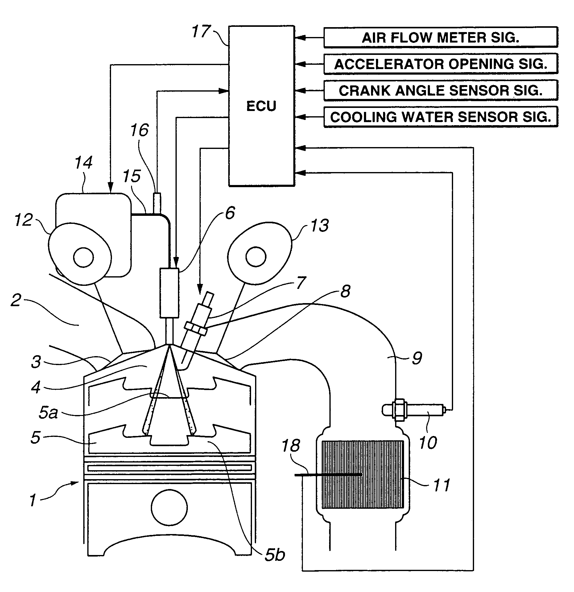
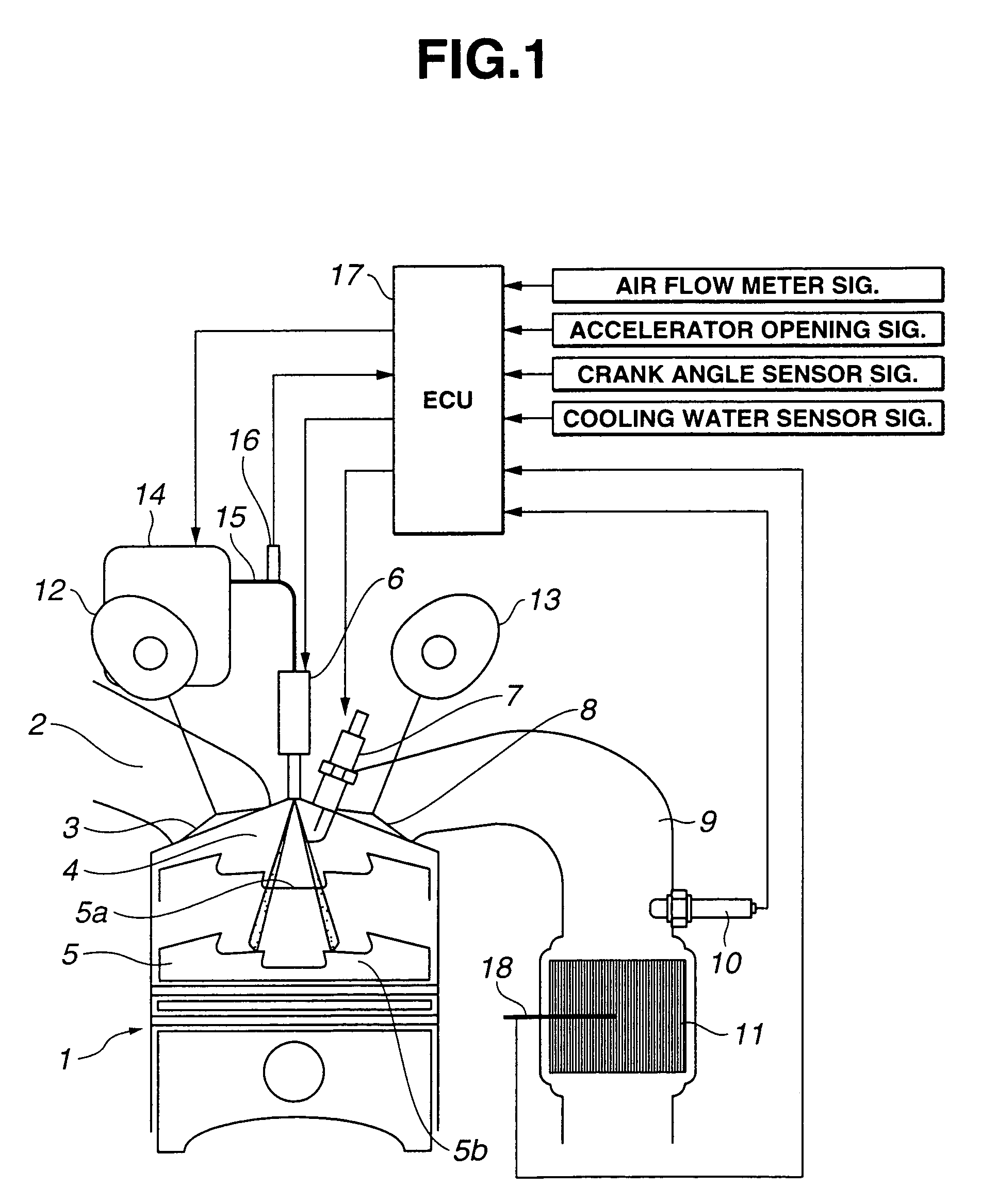
[0022]FIG. 1 is a schematic diagram representing a configuration of an exhaust emission control apparatus for an internal combustion engine according to the present invention. At first, the exhaust emission control apparatus according to the present invention will now be explained.

[0023]An internal combustion engine 1 sucks fresh air from an intake port 2 into a combustion chamber 4 when an intake valve 3 is open. A piston 5 which does a reciprocating motion, is provided below combustion chamber 4. On the other hand, a fuel injection valve 6 and an ignition plug (spark plug) 7 are provided above combustion chamber 4. Fuel injection valve 6 carries out a fuel injection, and ignition plug 7 ignites air-fuel mixture. Fuel injection valve 6 is placed (attached) substantially at a midpoint above combustion chamber 4 so that fuel injection valve 6 faces in a downward direction. Ignition plug 7 is placed in a region right above after-mentioned cavities 5a and 5b so that ignition plug 7 pro...

second embodiment

[0046]In this case where the catalyst's temperature rise is required in this second embodiment, there are the following three patterns as shown in FIG. 5B. Pattern 1 is a case where the total fuel quantity is injected into the outer cavity without a split of fuel. Pattern 2 is a case where a portion of the total fuel quantity (the total fuel quantity×a split ratio Ksp) is precedently injected during the suction stroke. Pattern 3 is a case where a portion of the total fuel quantity (the total fuel quantity×split ratio Ksp) is injected into the inner cavity during the latter half of the compression stroke.

[0047]FIG. 6 is a flowchart showing a control process in ECU 17 in this second embodiment. Steps Sa1˜Sa4 are respectively same as steps S1˜S4 shown in FIG. 3 except that fuel pressure Pf is also read at step Sa1. Hence, the explanation of these steps will be omitted from the following description. At next step Sa5, the controller determines whether or not current catalyst temperature...

third embodiment

[0062]FIG. 8 is a flowchart showing a control process in ECU 17 in the At step Sb1, a key switch is turned ON and then a starter is started by turning the key to a start position for the starter (starter switch ON). Then the engine starts a cranking. At next step Sb2, the controller carries out a cylinder identification (discrimination) by using the crank angle sensor and a cam angle sensor which receive signals in dependence upon the engine rotation. At step Sb3, the controller reads intake air quantity QM, engine rotation speed NE, a cooling water temperature Tw, fuel pressure Pf, and an each cylinder's cycle number Ncyl counted from a first explosion. For information, this cycle number Ncyl can be determined from e.g., an injection number of the fuel injection valve or an ignition number of the ignition plug.

[0063]At next step Sb4, the controller calculates target torque TTC in accordance with engine rotation speed NE and cooling water temperature Tw. Next at step Sb5, the contr...


PUM


Abstract

An exhaust emission control apparatus for an internal combustion engine includes a fuel injection valve placed substantially at a midpoint above a combustion chamber of the engine; a piston having an outer cavity formed substantially in a midsection of an upper surface of the piston and an inner cavity formed in a bottom surface of the outer cavity; an ignition plug placed in a region right above the outer cavity; an exhaust purifying catalyst provided in an exhaust passage of the engine; and a controller. This controller is configured to carry out a stratified charge combustion when a temperature rise for the exhaust purifying catalyst is required, by forming air-fuel mixture which is richer than stoichiometric ratio and is able to be ignited by the ignition plug, within the outer cavity and in an area substantially right above the outer cavity, from a fuel injected through the fuel injection valve.

Description

BACKGROUND OF THE INVENTION[0001]The present invention relates to exhaust emission control apparatus and method for a direct-injection and spark-ignition type internal combustion engine. More particularly, the present invention relates to a temperature rising technique for early activating an exhaust purifying catalyst provided in an exhaust passage.[0002]There is an internal combustion engine which performs a lean burn by injecting fuel directly into a cylinder from a fuel injection valve and then forming stratified air-fuel mixture within the cylinder at the time of a spark-ignition combustion. Such an internal combustion engine can reduce fuel consumption specifically under a low or middle load condition. Moreover, some earlier technologies with respect to the above-mentioned direct-injection and spark-ignition type internal combustion engine, have been proposed to accelerate the activation of the exhaust purifying catalyst during a cold start and a warm-up process of the engine....

Claims


Application Information

Patent Timeline
Patent Type & Authority Patents(United States)
IPC IPC(8): F02B17/00
CPCF02D41/024F02D41/3023F02P5/1502Y02T10/26Y02T10/46F02D2200/0602Y02T10/12Y02T10/40
Inventor SHIRAISHI, TAISUKEHIRAYA, KOJIHOTTA, ISAMUTANAKA, DAISUKE
Owner NISSAN MOTOR CO LTD
Why Eureka
Try Eureka