Smoke generating apparatus

a technology of smoke generating liquid and generating apparatus, which is applied in the direction of lighting and heating apparatus, container discharge methods, instruments, etc., to achieve the effect of improving the vapourization of the smoke generating liquid

Inactive Publication Date: 2000-11-07
CPS PRODS +1
View PDF5 Cites 27 Cited by
  • Summary
  • Abstract
  • Description
  • Claims
  • Application Information

AI Technical Summary

Benefits of technology

The smoke generating apparatus, as described above, deposits a fine mist-like spray of smoke generating liquid onto a heated substrated, such as a conductive coil. The risk of an electrical connection being made by a geyser of smoke generating liquid is eliminated. Where a lower portion of the housing serves as the liquid reservoir, the nozzle can be positioned within the liquid reservoir with the nozzle partially submerged in the smoke generating liquid. The reservoir can also be positioned in a separate liquid retaining portion of the housing or completely outside of the housing. As a further safety feature it is preferred that the conductive coil be insulated from the housing.
Although beneficial results have been obtained through the use of the smoke generating apparatus, as described above, improved smoke generation have been obtained when two additional features are provided. When the conductive coil coils around a central axis and the outlet end of the spray nozzle is positioned along the axis, improved vapourization of the smoke generating liquid has been obtained. When means are provided to adjust the relative spacing between the outlet end of the spray nozzle and the conductive coil, the vapourization of the smoke generating liquid can be further improved.
There are different ways to construct a nozzle so that the passage of gaseous medium through the nozzle will draw smoke generating liquid from the reservoir. What is required is a pressure drop at the nozzle outlet that will serve to draw liquid from the reservoir. This can be achieved by placing a restriction at an outlet end of a liquid flow passage extending through the nozzle. The flow of gaseous medium through the nozzle effects the efficiency of the nozzle in drawing liquid. Beneficial results have been obtained by providing within the nozzle a gaseous medium flow passage. The gaseous medium flow passage has an inlet portion and an outlet portion. The outlet portion of the gaseous medium flow passage divides into at least two branch passages. The lifting force of the gaseous medium is best when the sum of the cross-sectional areas of the outlet portions is substantially equal to the cross-sectional area of the inlet portion. It is undesirable for any vortex to be caused in the nozzle outlet. It is, therefore, preferred that the branch passages be positioned adjacent the outlet end of the liquid flow passage and that means be provided to deflect the flow of gaseous medium from the branch passages of the gaseous medium flow passage to provide a substantially linear flow through the outlet end of the nozzle.

Problems solved by technology

There have been recorded incidents of explosions occurring when the geyser of liquid served to complete a circuit through which electricity could flow.

Method used


Image

  • Smoke generating apparatus
  • Smoke generating apparatus
  • Smoke generating apparatus

Examples


Embodiment Construction

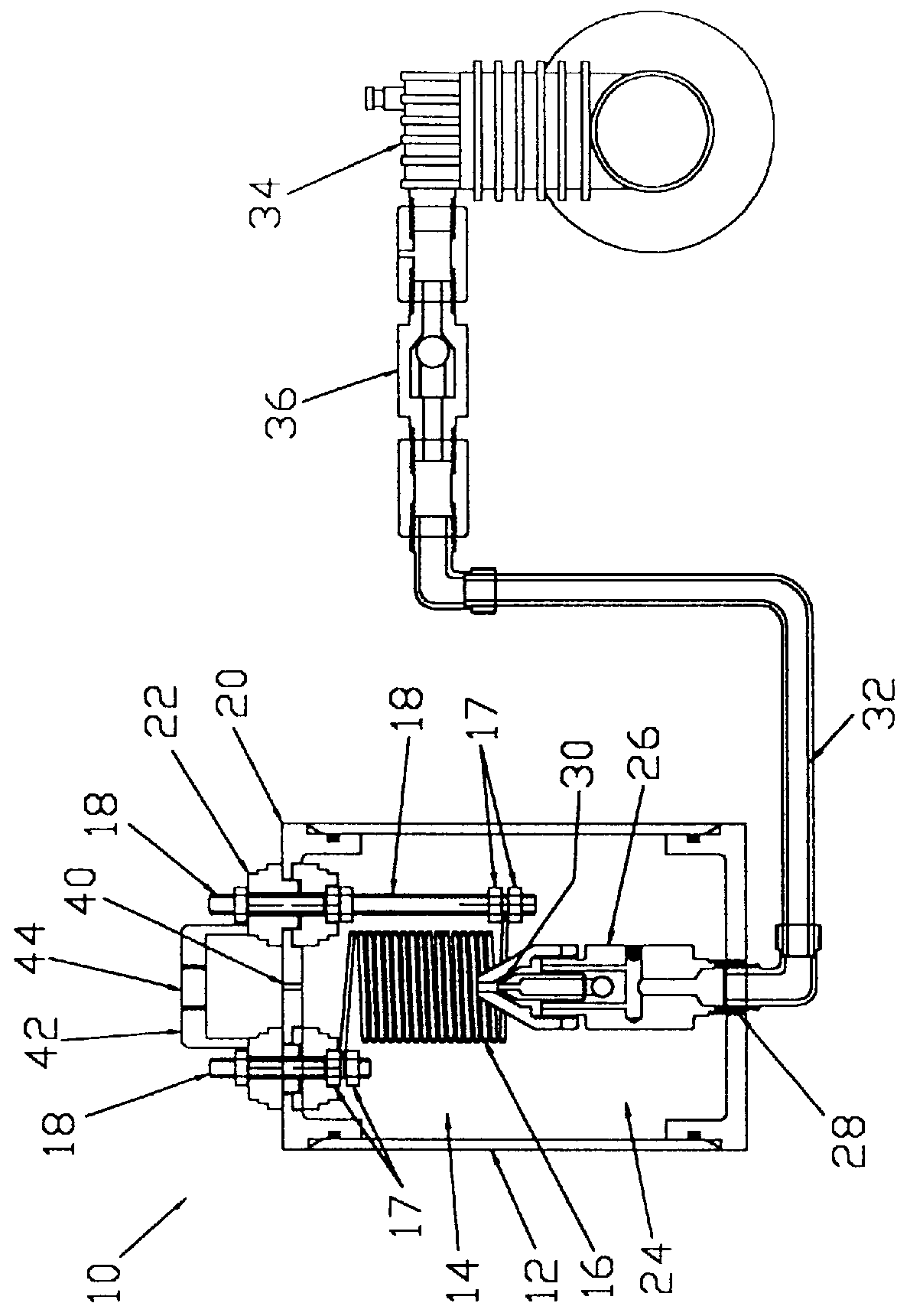
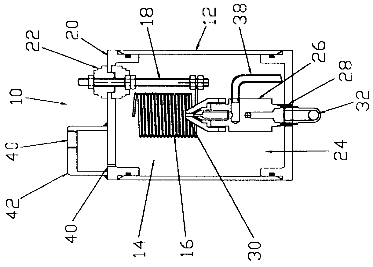
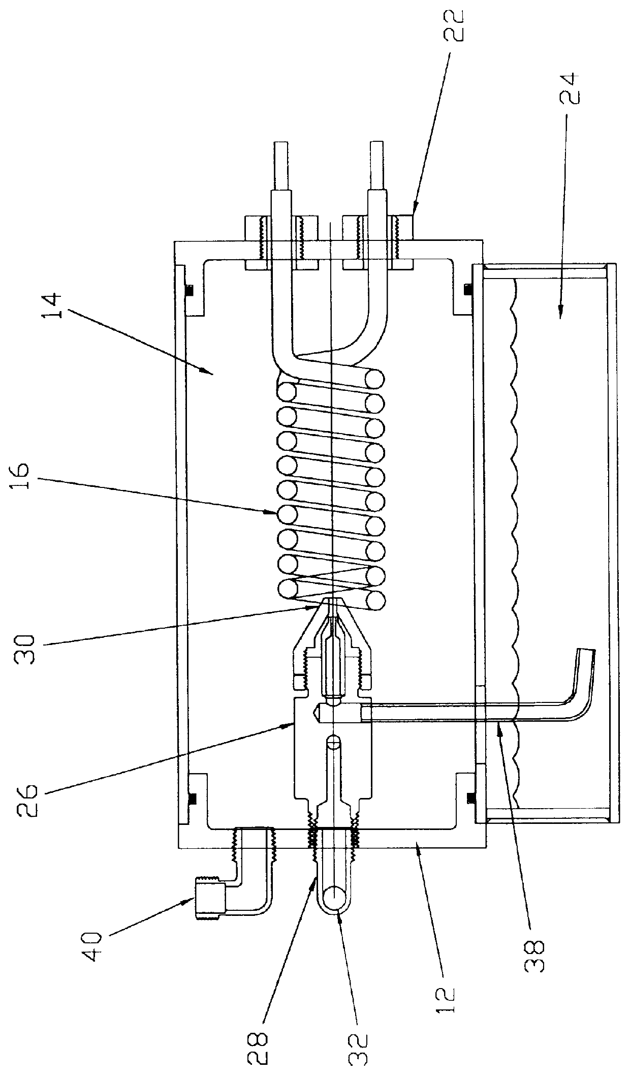
The preferred embodiment, a smoke generating apparatus generally identified by reference numeral 10, will now be described with reference to FIGS. 1 through 5.

Referring to FIG. 1, smoke generating apparatus 10 includes a housing 12 having an interior cavity 14. A heated substrate, such as conductive coil 16 is secured by nuts 17 to mounting posts 18 which extend down from a top 20 of housing 12. This manner of mounting positioned conductive coil 16 so that it extends down into interior cavity 14. When working with 120 volt or 240 volt power sources, it is preferred that conductive coil 16 have an insulated coating. With battery operated units having lower operating voltages an insulated coating of conductive coil 16 is not viewed as being as critical. Insulators 22 are positioned between mounting posts 18 and housing 12 to insulate conductive coil 16 from housing 12. That portion of interior cavity 14 of housing 12 that is positioned below conductive coil 16 serves as a reservoir, g...


PUM


Abstract

A smoke generating apparatus includes a housing having an interior cavity. A heated substrate is disposed within the interior cavity of the housing. A reservoir is provided to hold smoke generating liquid. An atomizing nozzle is disposed within the interior cavity of the housing. The nozzle has an inlet end and an outlet end. The outlet end points toward the heated substrate, such that fluid medium discharged through the outlet of the nozzle strikes the heated substrate. The inlet end of the nozzle is coupled to a source of gas under pressure. A liquid flow passage is provided which connects the nozzle with the reservoir. A flow of gaseous medium through the nozzle atomizes smoke generating liquid drawn from the reservoir.

Description

FIELD OF THE INVENTIONThe present invention relates to a smoke generating apparatus.BACKGROUND OF THE INVENTIONU.S. Pat. No. 5,107,698 which issued to Gilliam in 1992 discloses a smoke generating apparatus. Smoke generating apparatus, such as those disclosed by Gilliam, are used to test for hairline cracks and similar leaks that are not detectable by visual inspection. The location of the leak is detected by observing smoke exiting from the leak. The Gilliam apparatus has a container in which is disposed a heating element. The container is filled with a smoke producing liquid until the liquid level reaches, without submerging, the heating element. An air pump forces a flow of air to bubble up through the smoke producing liquid, propelling a geyser of the smoke producing liquid into contact with the heating element. A portion of the smoke producing liquid coming in contact with the heating element is vaporized. When the smoke producing liquid is vaporized, it becomes smoke. As the fl...

Claims


Application Information

Patent Timeline
Patent Type & Authority Patents(United States)
IPC IPC(8): G01M3/22G01M3/20
CPCG01M3/228G01M3/226
Inventor LOBLICK, NORTON MARCUS
Owner CPS PRODS
Why Eureka
Try Eureka