Supercharge Your Innovation With Domain-Expert AI Agents!

Tire preparation ply manufacturing apparatus and method

a technology of manufacturing apparatus and tires, applied in the direction of photosensitive materials, mechanical control devices, instruments, etc., can solve the problem of not being suitable for butt splicing, and achieve the effect of simple design, less cost and high quality

Inactive Publication Date: 2006-07-11
THE GOODYEAR TIRE & RUBBER CO
View PDF43 Cites 7 Cited by
  • Summary
  • Abstract
  • Description
  • Claims
  • Application Information

AI Technical Summary

Benefits of technology

[0007]In a first embodiment of the present invention, an apparatus is provided that automatically butt splices a preparation ply having metallic or nonmetallic reinforcing cords. The apparatus is relatively simple in design and less expensive than other machinery used to butt splice a preparation ply. The apparatus of the present invention provides a high quality butt splice regardless of the reinforcing cord material and therefore, is especially useful in making a preparation ply having nonmetallic reinforcing cords.
[0010]In a second embodiment of the present invention, an apparatus is provided that automatically applies a gum strip to a butt joint joining two preparation plies together. The apparatus is fast, reliable and automatically operable with the butt splicer described herein and therefore, is especially useful in making a preparation ply having nonmetallic reinforcing cords.
[0013]In a third embodiment of the present invention, an apparatus is provided that automatically forms a continuous preparation ply of the type used to make vehicle tires from preparation ply sections having nonmetallic cords. Being able to economically, efficiently and reliably butt splice preparation plies provides a higher quality tire manufacturing process.

Problems solved by technology

However, if the elastomeric material has nonmetallic reinforcing cords, the lateral calendered edges of the material are not straight but undulating.
Such curved calendered edges provide a nonuniform and variable gap between the adjacent ends of the pieces and thus, are generally not considered suitable for a butt splice.

Method used


Image

  • Tire preparation ply manufacturing apparatus and method
  • Tire preparation ply manufacturing apparatus and method
  • Tire preparation ply manufacturing apparatus and method

Examples


Embodiment Construction

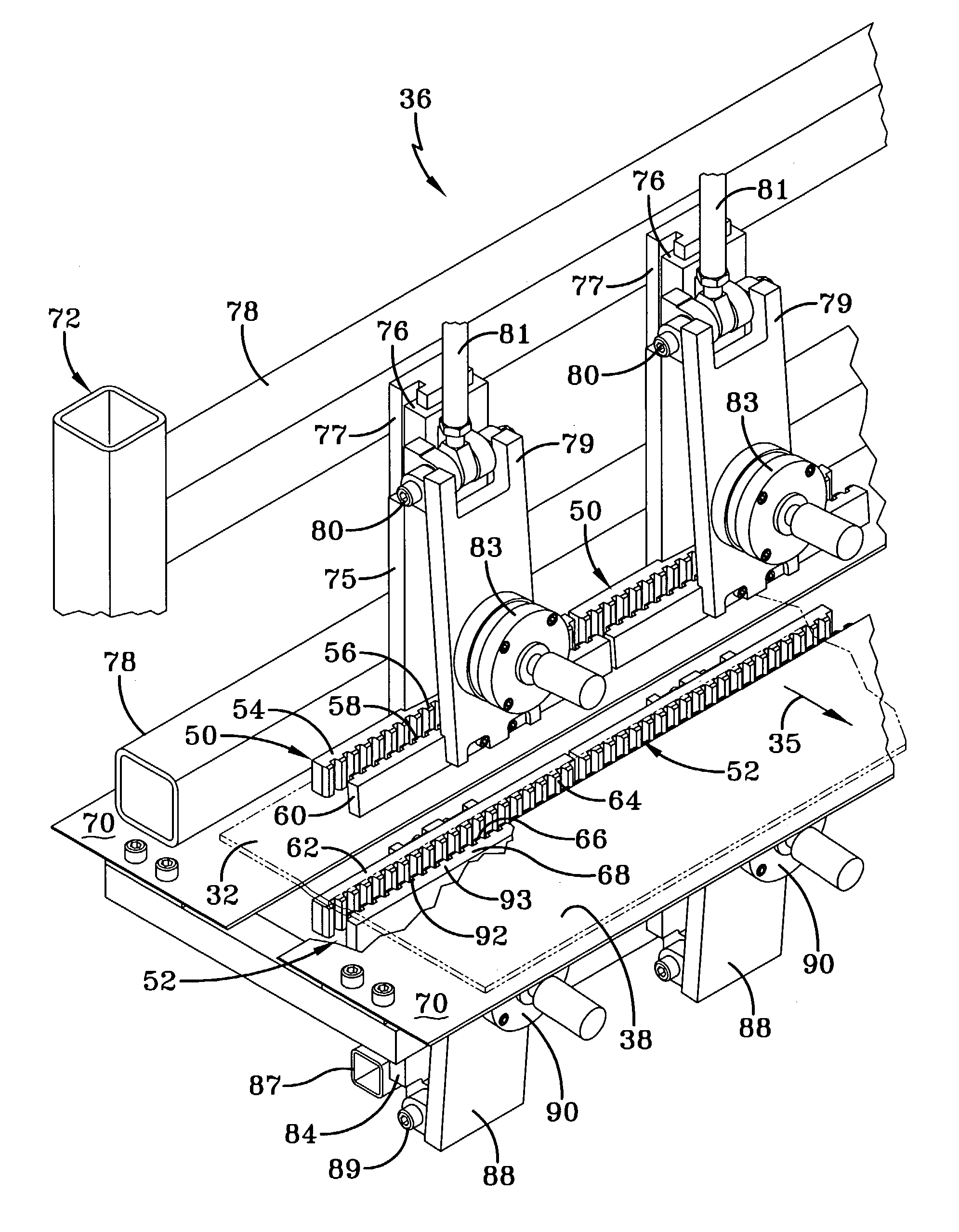
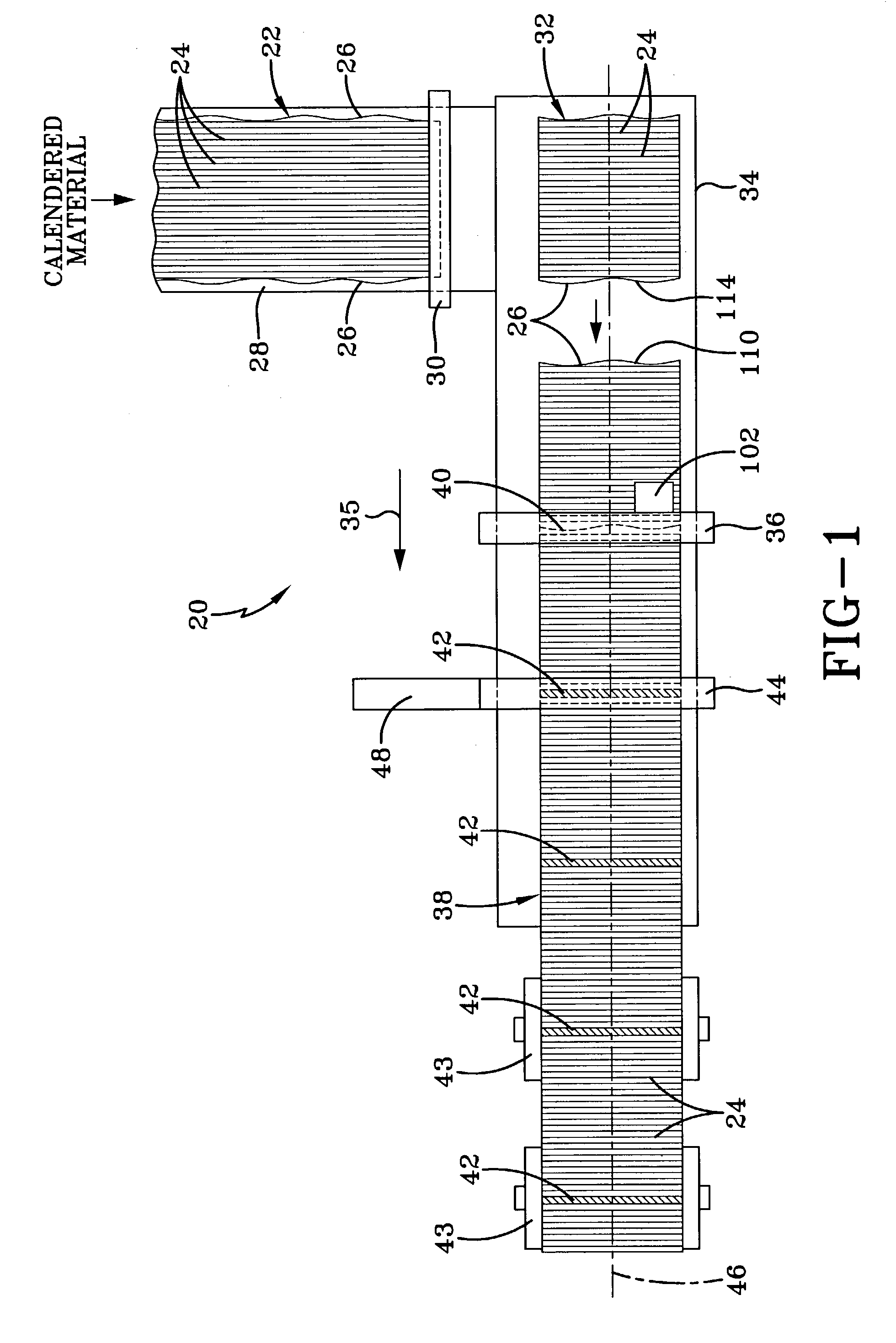
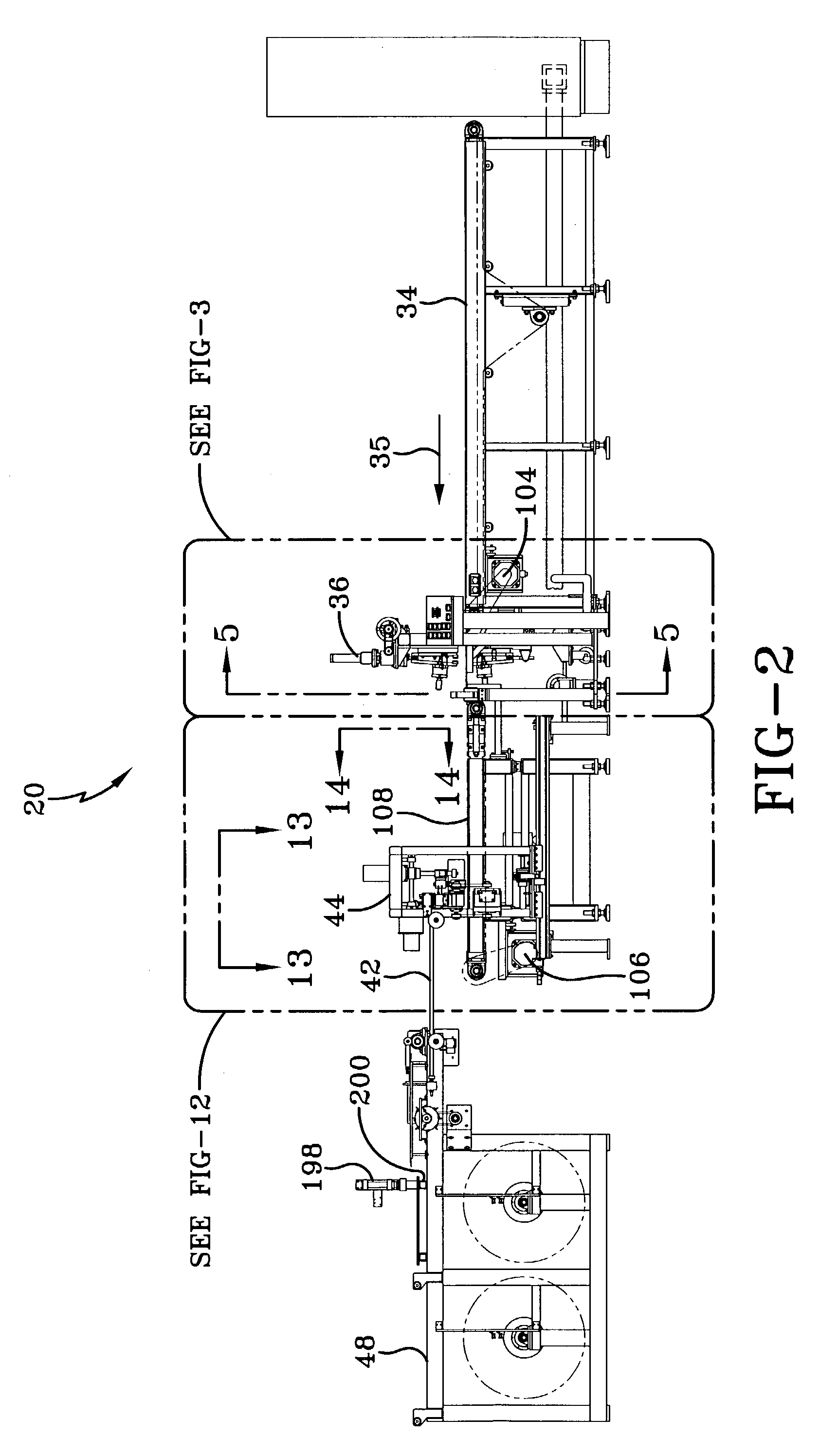
[0035]Referring to FIG. 1, in a preparation ply manufacturing line 20, a strip of calendered material 22 is fed from calender rolls (not shown) in a known manner. The calendered material 22 is about 0.040–0.060 inch thick and has cords 24 made from a nonmetallic material, which extend longitudinally generally parallel to the calendered edges 26. The nonmetallic cords 24 being less rigid than metallic cords result in the calendered edges 26 being nonlinear and undulating. The calendered material is fed by a conveyor 28 past a cutter 30, which cuts the calendered material to desired lengths, depending on the application. The resulting rectangular pieces 32 are then transferred onto a transverse infeed conveyor 34. The pieces are then conveyed in a downstream direction 35 to a butt splicing machine 36 that forms butt joints 40 between the calendered edges 26 of the cut pieces 32 to form a continuous preparation ply strip 38. The butt joints 40 are reinforced by respective gum strips 42...


PUM


Abstract

An apparatus for forming a continuous preparation ply of the type used to make vehicle tires from preparation ply sections having nonmetallic cords. An infeed conveyor successively feeds the preparation ply sections to a butt splicing machine that joins the ends of the two preparation ply sections to form a butt joint. A gum strip applier receives the continuous preparation ply from an outfeed conveyor and applies a gum strip over the butt joint. A method is provided for forming a continuous preparation ply by first automatically forming a butt joint, and thereafter automatically placing a gum strip on the butt joint.

Description

FIELD OF THE INVENTION[0001]This invention relates generally to apparatus and method for producing a continuous preparation ply material for making tires and more particularly, to an apparatus and method for making a continuous web of preparation ply material having transverse nonmetallic reinforcing cords.BACKGROUND OF THE INVENTION[0002]In the construction of a radial ply tire, a carcass consisting of one or more preparation plies of elastomeric material is built up on a generally cylindrical drum. The preparation ply is applied so that reinforcing cords run from bead to bead in a direction that is generally parallel to the axis of the drum. Thus, prior to making the carcass, the preparation ply with the transversely extending reinforcing cords must first be made.[0003]It is known to manufacture the preparation ply by first producing a sheet of elastomeric material in which reinforcing cords extend longitudinally. During production, the sheet of elastomeric material passes between...

Claims


Application Information

Patent Timeline
IPC IPC(8): B29C65/56B29D30/38B29C65/00B29D30/42
CPCB29C65/00B29C66/1142B29C66/43B29D30/42B29D2030/381B29C66/964Y10T156/1749B29D2030/422B29K2021/00B29L2030/003Y10S156/906B29C65/483B29C65/5042B29C65/5092B29C65/7802B29C65/7841B29C65/7847B29C66/435B29C66/71B29C66/7212B29C66/72141B29C66/73752B29C66/8221B29K2305/00
Inventor DYRLUND, CHRISTOPHER DAVIDKUBINSKI, DONALD CHESTERBULL, JEFFREY FORDEDWARDS, FRANK A.
Owner THE GOODYEAR TIRE & RUBBER CO
Features
  • R&D
  • Intellectual Property
  • Life Sciences
  • Materials
  • Tech Scout
  • Unparalleled Data Quality
  • Higher Quality Content
  • 60% Fewer Hallucinations
Learn More