Disk brake with mechanical self-boosting

a self-boosting, disc brake technology, applied in the direction of axially engaging brakes, brake types, actuators, etc., can solve the problems of affecting the smooth running of the caliper guide, force to be transmitted from the caliper guide upon braking, etc., to achieve easy adjustment of air clearance, reduce brake lining wear, and facilitate the restoration of the caliper

Inactive Publication Date: 2006-07-11
ROBERT BOSCH GMBH
View PDF6 Cites 10 Cited by
  • Summary
  • Abstract
  • Description
  • Claims
  • Application Information

AI Technical Summary

Benefits of technology

[0008]In the disk brake of the invention, the self-boosting mechanism is braced in a circumferential direction to the brake disk on the brake bracket and not on the caliper. As a result, a frictional or braking force exerted, when the disk brake is actuated, in the circumferential direction on the friction brake lining by the rotating brake disk is transmitted to the brake bracket and does not put a load on the caliper guide which guides the caliper displaceably on the brake bracket transversely to the brake disk. As a result, the caliper guide is substantially free of force; in particular, it need not transmit the high braking forces that occur during braking. As a result, the caliper guide can be comparatively small, and its smooth running is unimpaired by forces exerted on it. Another advantage is easier restoration of the caliper after a brake actuation, and in particular easier adjustment of the air clearance, which is due to the smooth running of the caliper guide. In addition, reduced brake lining wear when the disk brake is unactuated can be expected.

Problems solved by technology

At the same time, the force to be transmitted from the caliper guide upon braking impairs smooth running of the caliper guide.

Method used


Image

  • Disk brake with mechanical self-boosting
  • Disk brake with mechanical self-boosting
  • Disk brake with mechanical self-boosting

Examples


Embodiment Construction

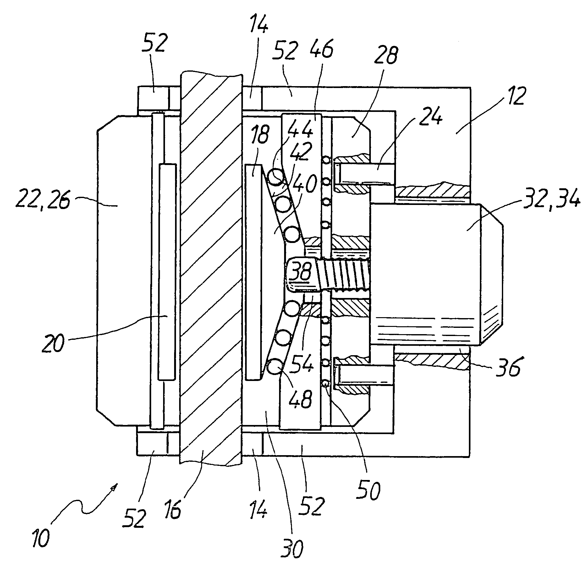
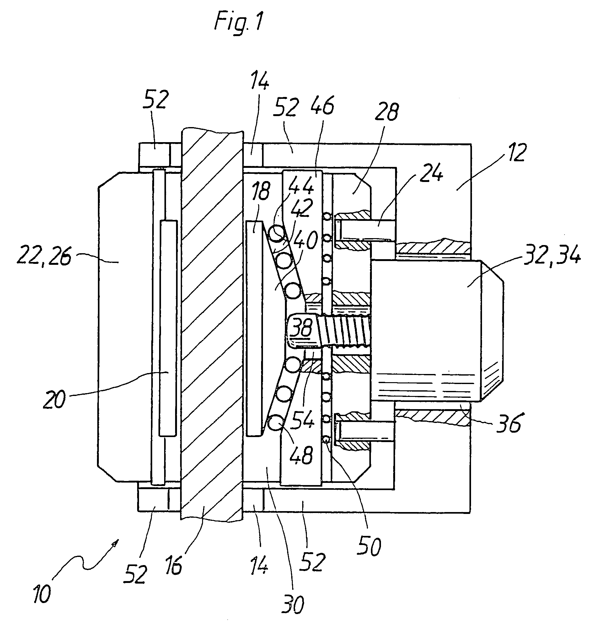
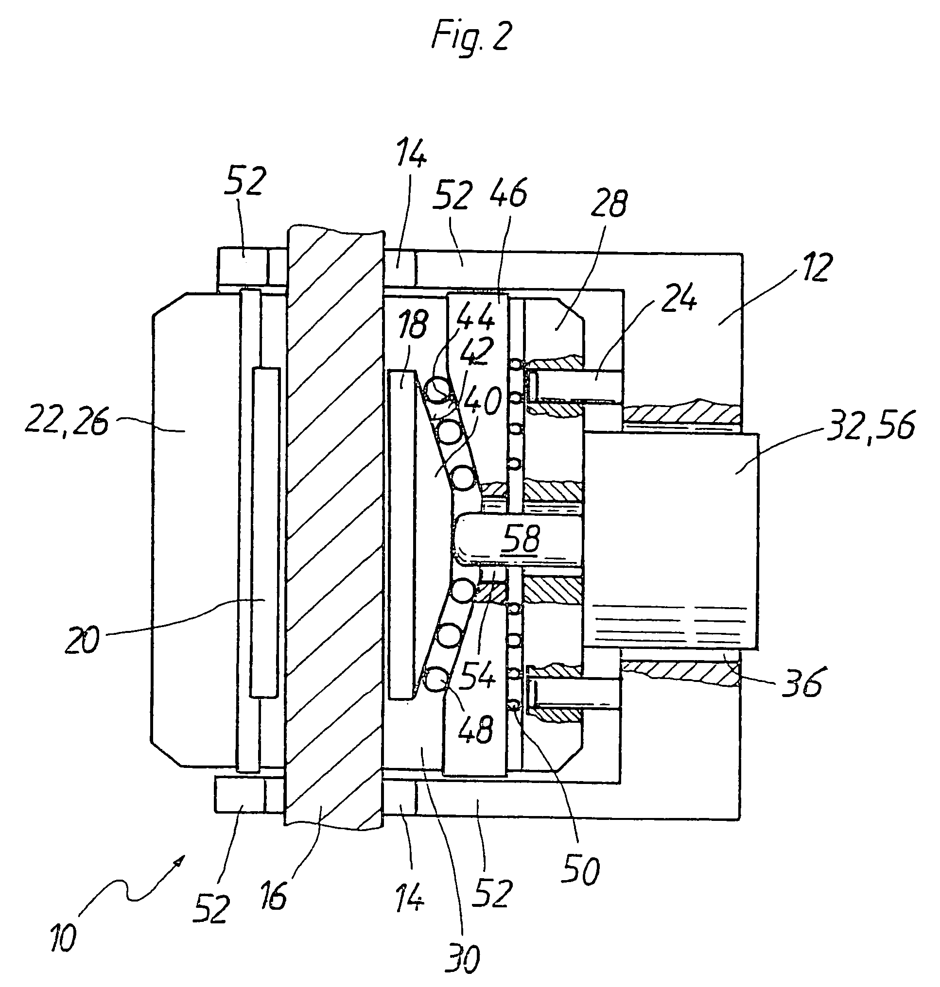
[0013]The disk brake 10 of the invention, shown in the drawing, has mechanical self-boosting and is actuated electromechanically. It is intended for use in a motor vehicle, not shown. The disk brake 10 has a brake bracket 12, which is firmly bolted or screwed for instance to one steering knuckle (not shown) of a motor vehicle. The brake bracket 12 has a recess 14 on both sides, and with them it fits over a brake disk 16 on the circumference. On both sides of the brake disk 16, the brake bracket 12 protrudes radially approximately as far inward as friction brake linings 18, 20 of the disk brake 10, which are disposed one on each side of the brake disk 16.

[0014]A caliper 22 rests in the brake bracket 12 and is guided displaceably with a caliper guide 24 transversely to the brake disk 16 in the brake bracket 12. The caliper guide 24, in the exemplary embodiment of the invention shown and described, is embodied as a rod guide. Because of its transverse displaceability, the caliper 22 ca...


PUM


Abstract

An electromechanical disk brake with mechanical self-boosting for instance by a ramp mechanism, which is intended for use in motor vehicles in which the ramp mechanism is braced in a circumferential direction relative to a brake disk on a brake bracket, in order thereby to keep a caliper guide of a floating caliper free of frictional and braking forces of the disk brake.

Description

BACKGROUND OF THE INVENTION[0001]1. Field of the Invention[0002]The invention relates to a disk brake with mechanical self-boosting which is intended in particular for motor vehicles.[0003]2. Description of the Prior Art[0004]Hydraulically actuated disk brakes without self-boosting, which are currently conventional, have a brake bracket and a caliper. The brake bracket and the caliper are parts resting one inside the other; the brake bracket is mounted fixedly on one steering knuckle or the like of a vehicle and retains the caliper transversely displaceable to a brake disk by means of a caliper guide. As their actuating unit, hydraulic disk brakes have a piston-cylinder unit, in which the cylinder is usually part of the caliper. With the piston, a friction brake lining can be pressed against one side of the brake disk. A reaction force displaces the caliper transversely to the brake disk, and as a result the caliper presses a second friction brake lining against the other side of th...

Claims


Application Information

Patent Timeline
IPC IPC(8): F16D55/46F16D55/14F16D55/226F16D65/14F16D65/16F16D65/18
CPCF16D55/226F16D65/18F16D2127/10F16D2121/18F16D2121/02F16D55/14F16D55/46
Inventor BAUMANN, DIETMARHOFMANN, DIRKVOLLERT, HERBERTNAGEL, WILLIHENKE, ANDREASFOITZIK, BERTRAM
Owner ROBERT BOSCH GMBH
Why Eureka
Try Eureka