Quick-release pump module

a pump module and quick-release technology, applied in the field of pumps, can solve problems such as considerable downtim

Active Publication Date: 2006-07-11
KREBS ENGINEERS CORP +1
View PDF9 Cites 27 Cited by
  • Summary
  • Abstract
  • Description
  • Claims
  • Application Information

AI Technical Summary

Problems solved by technology

Removal of the wet end from the power frame and reassembly of the wet end therewith are time-consuming procedures which can take as long as 12 hours and result in considerable downtime.

Method used


Image

  • Quick-release pump module
  • Quick-release pump module
  • Quick-release pump module

Examples


Embodiment Construction

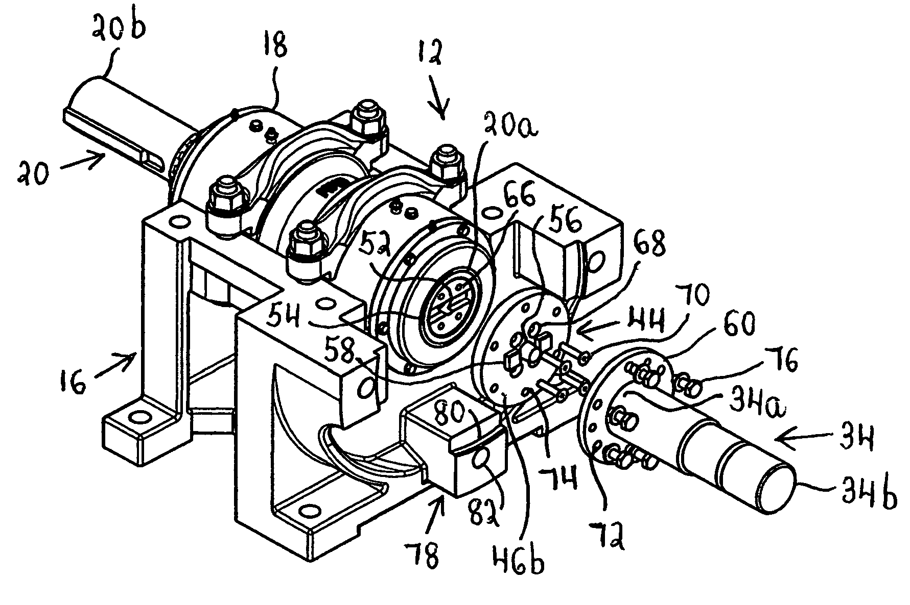
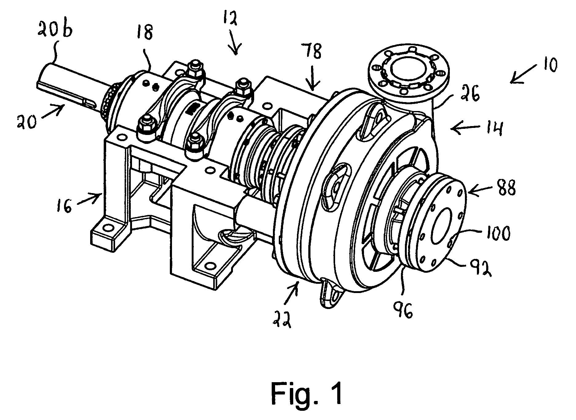
[0033]Referring to FIG. 1, the numeral 10 identifies a pump in accordance with the invention. The pump 10, which is here assumed to be a slurry pump for a mining or other industrial facility, includes a power frame or drive section 12 and a wet end or driven section 14 attached to the frame 12.

[0034]Considering FIG. 2 together with FIG. 1, the power frame 12 includes a pedestal or support 16 which carries a bearing assembly 18. A receiver shaft or drive member 20 is mounted for rotation in the bearing assembly 18, and the receiver shaft 20 has a drive end 20a which adjoins the wet end 14 and a driven end 20b which is remote from the wet end 14. The driven end 20b is adapted to be coupled to a non-illustrated motor.

[0035]For ease of bearing replacement, the drive end 20a of the receiver shaft 20 is located adjacent to the flinger which adjoins the wet end 14.

[0036]With regard to FIGS. 1, 3 and 4, the wet end 14 comprises a casing or housing 22 having a suction or intake port 24 and a...


PUM

PropertyMeasurementUnit
timeaaaaaaaaaa
diameteraaaaaaaaaa
diameteraaaaaaaaaa

Abstract

A slurry pump includes a power frame as well as a wet end, and the wet end comprises a casing, an impeller and wear ring in the casing, a stub shaft connected to the impeller, a sleeve assembly for the stub shaft and an adapter for adjusting the wet end to the power frame. The wet end can be attached to and detached from the power frame as a module.

Description

REFERENCE TO RELATED APPLICATION[0001]This application is based on provisional application Ser. No. 60 / 512,791 filed 20 Oct. 2003 by Dale E. Coray and Richard M. McGahee for “A Quick-Release Pump Module.”BACKGROUND OF THE INVENTION[0002]1. Field of the Invention[0003]The invention relates to a pump.[0004]2. Description of the Prior Art[0005]Slurry pumps typically include a power frame as well as a so-called wet end which is attached to the power frame. The power frame comprises a bearing assembly, and a drive shaft which is rotatably supported by the bearing assembly and is connected to a motor. The wet end, on the other hand, comprises a sealed casing which houses an impeller and is formed with a suction port and a discharge port. The impeller is mounted on a stub shaft which receives power from the drive shaft.[0006]When the wet end requires maintenance, the major components of the wet end are disconnected from the power frame individually and in the reverse order from which such ...

Claims


Application Information

Patent Timeline
Patent Type & Authority Patents(United States)
IPC IPC(8): F04B17/00B23P6/00F04D13/02F04D29/62
CPCF04D13/021F04D29/628Y10T29/49238
Inventor CORAY, DALE E.MCGAHEE, RICHARD M.
Owner KREBS ENGINEERS CORP
Why Eureka
Try Eureka