Land grid array socket having terminals with spring arms

a technology of spring arms and sockets, which is applied in the direction of coupling contact members, fixed connections, coupling device connections, etc., can solve the problems of insufficient resilient mating force, short length of mating beams, and easy damage of mating beams, so as to improve the safety of electrical connections, avoid short circuit risks, and high density array

Inactive Publication Date: 2006-07-11
HON HAI PRECISION IND CO LTD
View PDF9 Cites 58 Cited by
  • Summary
  • Abstract
  • Description
  • Claims
  • Application Information

AI Technical Summary

Benefits of technology

[0008]Accordingly, a main object of the present invention is to provide an land grid array (LGA) socket having electrical terminals, wherein the terminals enhance the safety of electrical connection between separate electronic components while maintaining a high density array in the socket.
[0009]To fulfill the above-mentioned object, a LGA socket in accordance with the present invention comprises an insulative housing having a plurality of passageways formed therein, the passageways are arrayed in several rows in a lateral direction and each have an electrical terminal accommodate therein. The terminal each has a base portion for securing the terminal in the passageway, a solder portion extending toward a bottom mounting surface of the insulative housing and a spring arm extending out of a top mating surface of the insulative housing. The spring arm is connected to the base portion via a connecting portion formed therebetween. The spring arm has an extending portion which extends upwardly in a essentially slant manner with respect to the base portion and has a bending portion formed at one end of the extending portion, and an extending direction of the bending portion is not parallel to an extending direction of the extending portion, i.e. there is an angle existed between the extending directions of the two different portion. Further, a contacting end is formed at one end of the bending portion. An extending direction of the contacting end is parallel to the extending direction of the extending portion. Thus, when the terminals are secured into corresponding passageways of the insulative housing, a contacting end of a terminal extends out of its passageway and extends along the lateral direction toward an adjacent passageway in a same row. The contacting end invades a space above the adjacent passageway, and because of bending of the bending portion, the contacting end does not completely locate right above the spring arm of the terminal in the adjacent passageway, but locates in the space beside the adjacent passageway, i.e. the two adjacent terminals do not overlap in a vertical direction. Therefore, when the terminals are pressed down to their final position, the contacting end in one passageway does not contact with the terminal in an adjacent passageway in the same row so as to avoid short circuit risk between the adjacent terminals.

Problems solved by technology

Due to the small size of the terminals, the mating beams are easily damaged because of large stress generated during mating of the beams with the electronic components.
However, as disclosed in FIGS. 6 and 7, when the electronic component is fully pressed down to the insulative housing, mating beams of the terminals are completely pressed into the terminal holes, length of the mating beams is relatively short, which can not provide sufficient resilient mating force as required.
However, as shown in FIGS. 8 and 9, when the mating beams of the two adjacent terminal are fully pressed down to their final positions, short circuit between two adjacent terminals might become possible if the mating beams of the terminals contact with each others, this kind of risk is unacceptable because it will badly destroy the electronic components connected with the LGA socket.

Method used


Image

  • Land grid array socket having terminals with spring arms
  • Land grid array socket having terminals with spring arms
  • Land grid array socket having terminals with spring arms

Examples


Embodiment Construction

[0015]Reference will now be made to the drawings to describe the present invention in detail.

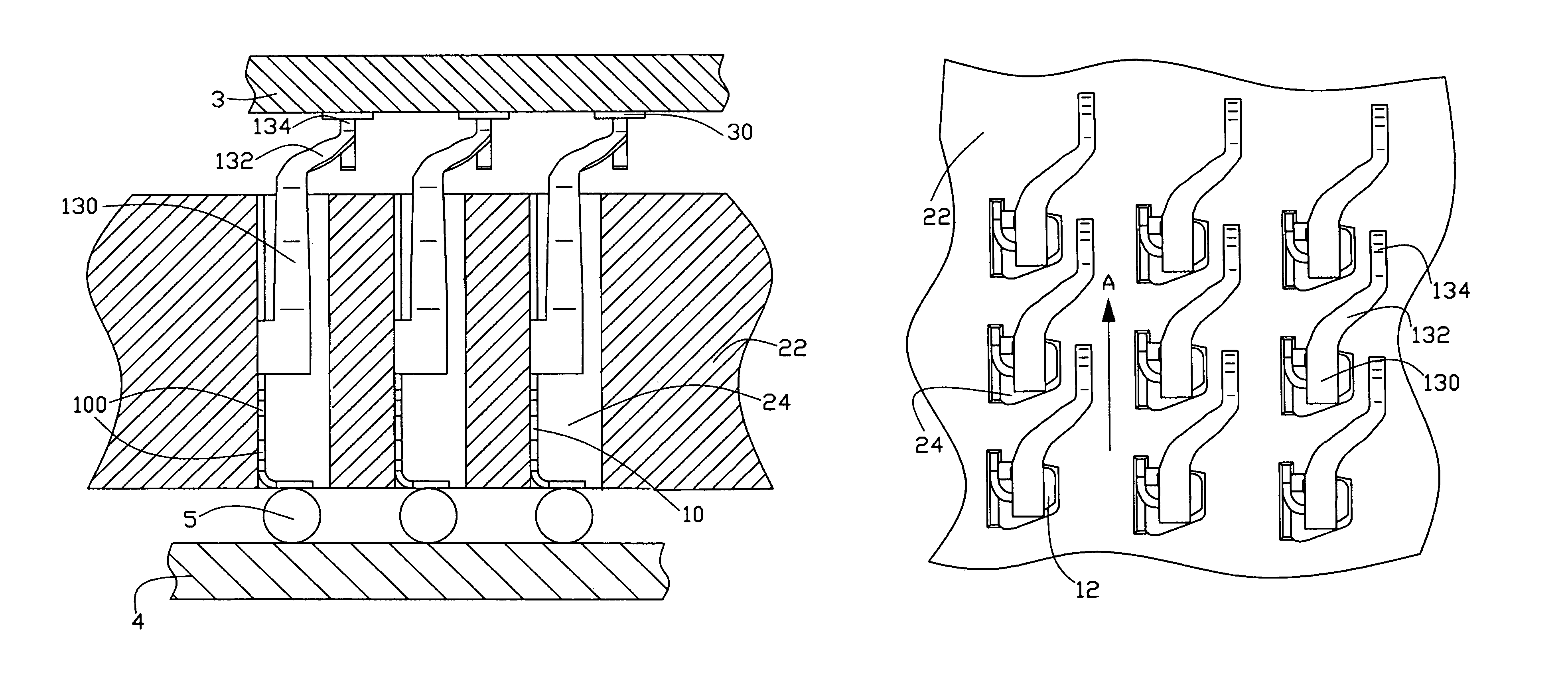
[0016]Referring to FIGS. 1 to 3, an electrical terminal 1 in accordance with the present invention is disclosed. Referring to FIGS. 4 and 5, a plurality of electrical terminal 1 as disclosed in FIGS. 1 to 3 are accommodated in corresponding passageways 24 of an insulative housing 22, respectively. The terminals 1 are arrayed in the housing 22 in rows such that the terminals 1 in a same row extends along a predetermined lateral direction “A”. In this embodiment, the insulative housing 22 and the terminals 1 basically forms a land grid array (LGA) socket to electrically connect an IC chip 3 and a motherboard 4.

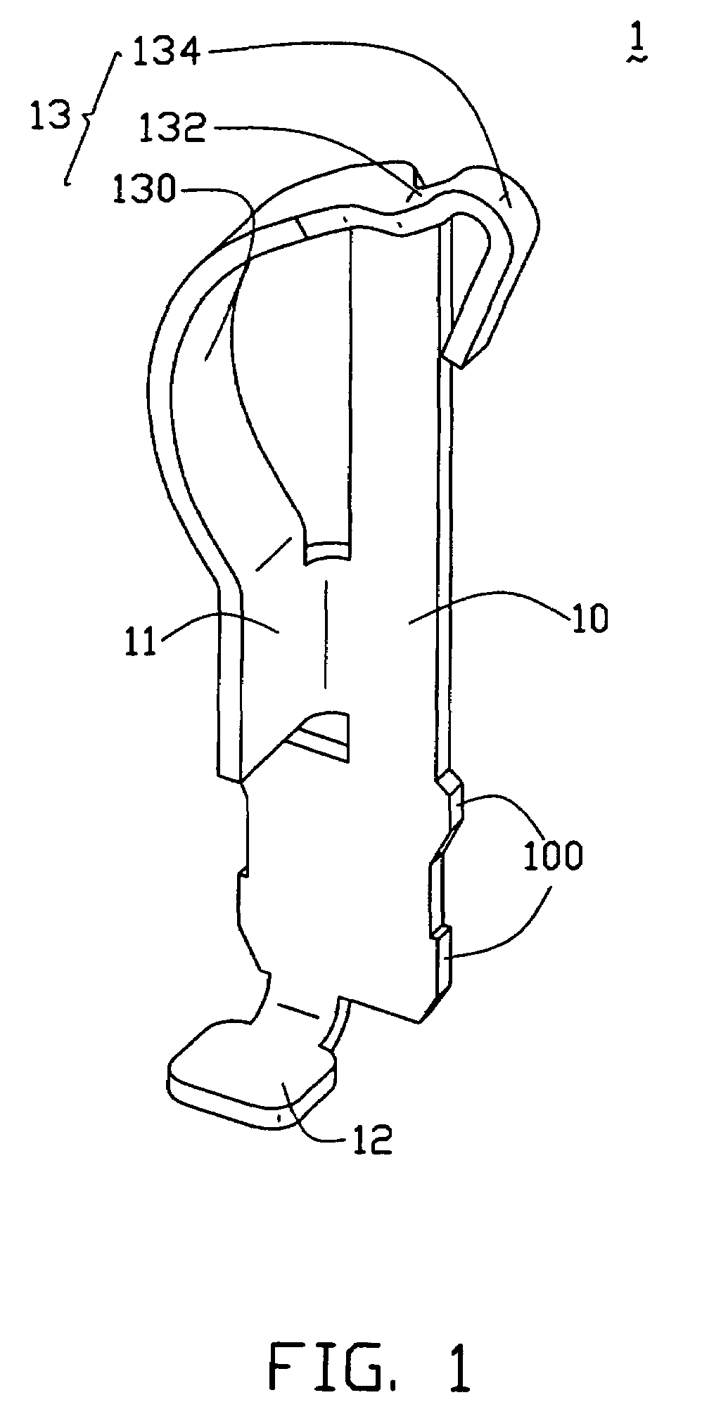
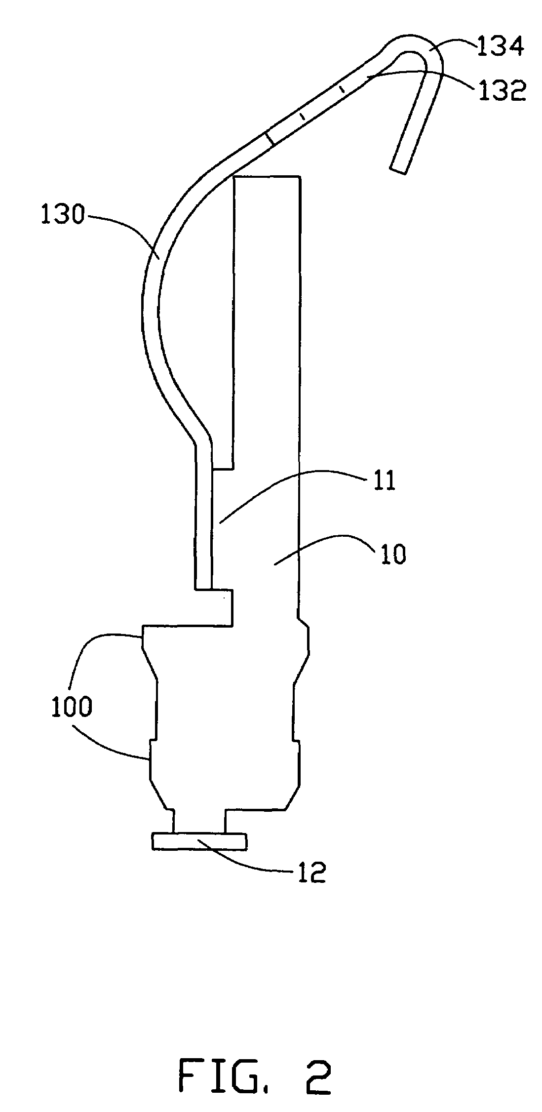
[0017]Referring to FIGS. 1 and 3, the terminal 1 comprises a base portion 10, a connecting portion 11, a solder portion 12 and a spring arm 13. The base portion 10 has a plurality of barbs formed in both sides thereof for securing the terminal 1 in the passageway 24. The connecting porti...


PUM


Abstract

A land grid array socket is provided which includes an insulative housing (22) having a plurality of passageways (24) each accommodating an electrical terminal (1) therein. Contacting ends (134) of the terminal in a same row of the passageways all extend along a predetermined lateral direction, and because of bend of a bending portion (132) in the terminal, the contacting end of the terminal in one passageway does not overlap with another terminal in an adjacent passageway along a vertical direction so as to avoid short circuit risk therebetween.

Description

CROSS REFERENCE TO RELATED APPLICATION[0001]This application is a continuation-in-part of U.S. patent application Ser. No. 10 / 625,237, filed on Jul. 22, 2003 now U.S. Pat. No. 6,805,561, entitled “ELECTRICAL SOCKET HAVING TERMINALS WITH ELONGATED MATING BEAMS”, a continuation-in-part of U.S. patent application Ser. No. 10 / 894,735 filed on Jul. 19, 2004, entitled “ELECTRICAL CONNECTOR WITH DUAL-FUNCTION HOUSING PROTRUSIONS”, a continuation-in-part of U.S. patent application Ser. No. 10 / 896,121, filed on Jul. 20, 2004 now U.S. Pat. No. 6,887,114, entitled “ELECTRICAL CONNECTOR WITH HIGH PERFOMANCE CONTACTS”, all of which have the same assignee.BACKGROUND OF THE INVENTION[0002]1. Field of the Invention[0003]The present invention relates to the art of electrical connectors, and more particularly to a land grid array (LGA) socket having terminals with elongated resilient mating arms.[0004]2. The Related Art[0005]It is well know that a land grid array (LGA) socket basically comprises an i...

Claims


Application Information

Patent Timeline
Patent Type & Authority Patents(United States)
IPC IPC(8): H01R12/00H01R13/24
CPCH01R13/2442H01R9/096H01R12/52H01R12/57
Inventor LIAO, FANG-JWUSZU, MING-LUNLEE, GENN-SHENG
Owner HON HAI PRECISION IND CO LTD
Why Eureka
Try Eureka