
Splice absorbing structure for motor vehicle

a technology for absorbing structures and motor vehicles, applied in the direction of contact members penetrating/cutting insulation/cable strands, electrical devices, coupling device connections, etc., can solve the problems of female terminal damage, complicated subsequent work, etc., and achieve the effect of reducing parts and production costs and simplifying the splicing step

Inactive Publication Date: 2006-07-11
SUMITOMO WIRING SYST LTD
View PDF11 Cites 15 Cited by
  • Summary
  • Abstract
  • Description
  • Claims
  • Application Information

AI Technical Summary

Benefits of technology

The present invention provides a splice absorbing structure for a motor vehicle that can flexibly accommodate changes in the number of cables to be spliced without requiring a separate terminal for each cable. The structure includes a cable holder that contains the ends of the cables in an aligned state and a sub connector with insulation displacement terminals that can be connected to the cables. The cables are spliced through the insulation displacement terminals when the sub connector is fitted into the joint connector housing. The structure also includes a joint connector housing with a plurality of sub connector containing sections and a joint bus bar with tuning fork terminal portions. The cables can be spliced through the joint bus bar when the sub connector is fitted into the joint connector housing. The cable holder includes a body and a lid joined by a hinge, with cable fitting grooves and cable latching portions for holding the cables in place. The cable holder also includes a partition with a terminal hole and a containing chamber for the tuning fork terminal portions of the joint bus bar. The invention simplifies the assembly process of the sub harnesses and prevents failure of the connection between the cables and the insulation displacement blades due to lack of cable insertion.

Problems solved by technology

This will make subsequent work complicated and may give rise to damage of the female terminal 4 during transportation of the sub harnesses.

Method used


Image

  • Splice absorbing structure for motor vehicle
  • Splice absorbing structure for motor vehicle
  • Splice absorbing structure for motor vehicle

Examples


Embodiment Construction

[0039]The following description of the preferred embodiment(s) is merely exemplary in nature and is in no way intended to limit the invention, its application, or uses.

[0040]Referring now to the drawings, an embodiment of a splice absorbing structure for a motor vehicle in accordance with the present invention will be described.

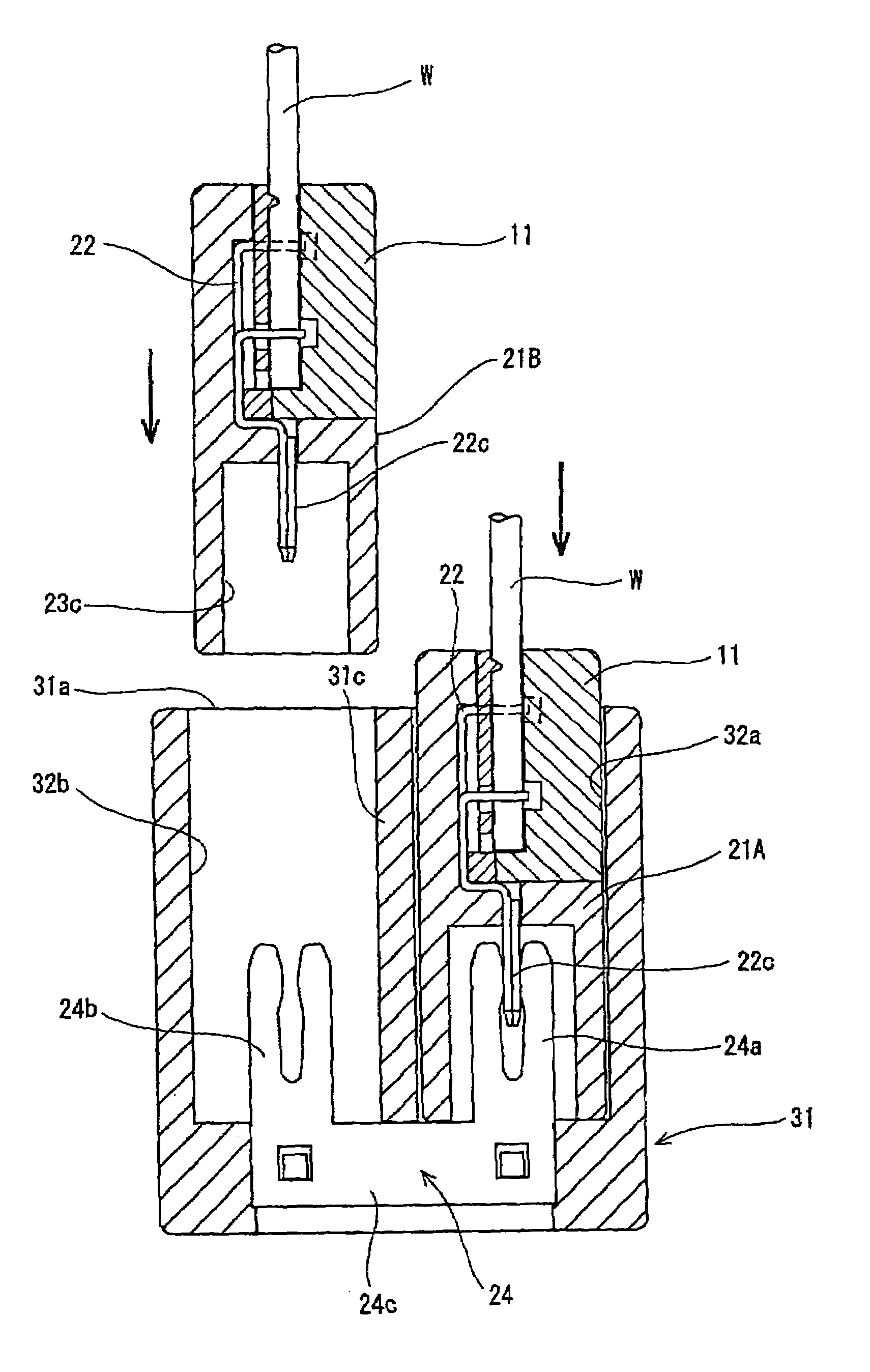
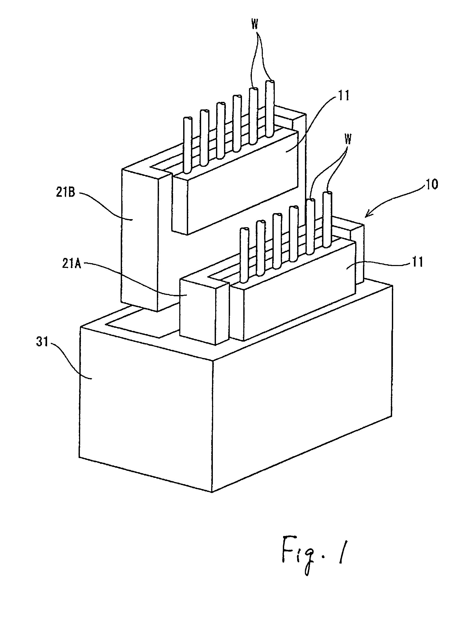
[0041]As shown in FIGS. 1 to 5, a motor vehicle splice absorbing junction box 10 includes a cable holder 11, that accommodates cables W to be spliced in a juxtaposed manner, sub connectors 21A and 21B, that accommodates the cable holder 11, and a joint connector housing 31, that accommodates the plural sub connectors 21A and 21B parallel to one another.

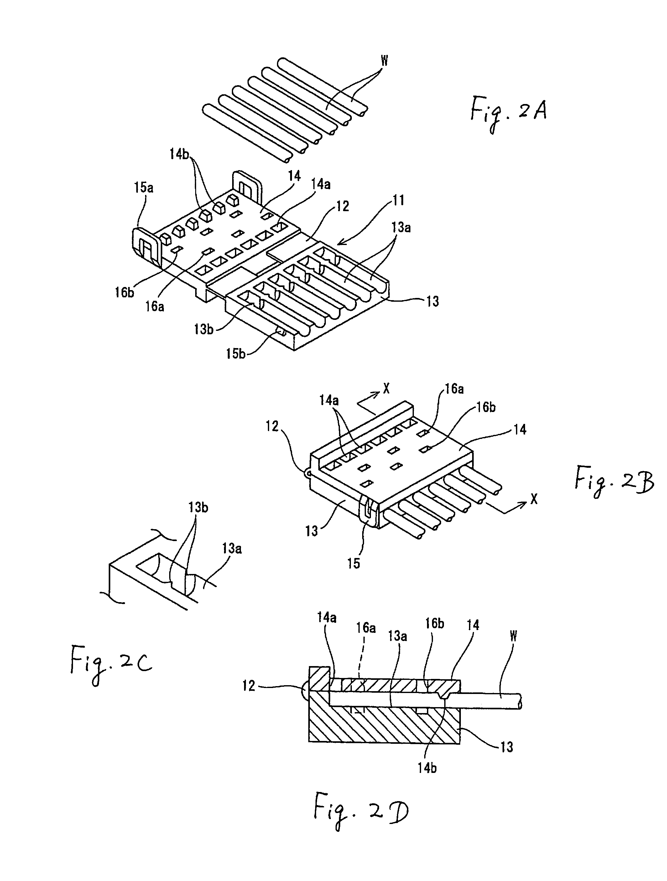
[0042]The cable holder 11, as shown in FIGS. 2A to 2D, is made of a synthetic resin material. The cable holder 11 includes a body 13 and a lid 14 pivotally coupled to each other through hinges 12. The body 13 includes a plurality of juxtaposed cable fitting grooves 13a that receive ends of the plural cables W p...


PUM


Abstract

Cables W are spliced to one another by insulation displacement terminals 22 in sub connectors 21A and 21B, when a cable holder 11 that contains ends of a plurality of cables is fitted into containing sections of the sub connector housings 21A and 21B. A tab 22c of each insulation displacement terminal 22 is connected to each joint bus bar 24 disposed in a joint connector housing 31. The sub connectors 21A and 21B are interconnected when the sub connectors 21A and 21B are fitted into containing sections of the joint connector housing 31.

Description

CROSS-REFERENCE TO RELATED APPLICATIONS[0001]The entire disclosure of Japanese Patent Application No. 2003-349075 filed on Oct. 8, 2003 including the specification, claims, drawings and summary is incorporated herein by reference in its entirety.FIELD OF THE INVENTION[0002]This invention relates to a splice absorbing structure for a motor vehicle and, more particularly, to a splice absorbing structure where splices between cables of sub harnesses can be flexibly adapted to various circuit connection configurations.BACKGROUND OF THE INVENTION[0003]Joint connectors have been utilized in order to splice cables to be used in a common circuit system in a wire harness. FIG. 9 shows a conventional joint connector 1. A spliced bus bar 2, adapted to various connection configurations, is mounted in a housing 1a. A mating connector 3 is engaged with the joint connector 1 and includes a female housing 3b with a plurality of cavities 3a formed in multiple stages. A female terminal 4 is to be ins...

Claims


Application Information

Patent Timeline
Patent Type & Authority Patents(United States)
IPC IPC(8): H01R11/09H01R4/24H01R13/518H01R31/08
CPCH01R31/085H01R4/2433
Inventor SAKA, YUUJISHIRAFUJI, YUKIHIROITO, TAKEHARU
Owner SUMITOMO WIRING SYST LTD
Learn More