Fiber-optic current sensor

a current sensor and fiber optic technology, applied in the field of fiber optic current sensors, can solve the problems of complex sensor construction, simple modulation units, and low stability of piezoelectric modulators, and achieve good long-term stability

Inactive Publication Date: 2006-07-11
ABB RES LTD
View PDF9 Cites 14 Cited by
  • Summary
  • Abstract
  • Description
  • Claims
  • Application Information

AI Technical Summary

Benefits of technology

The invention is a fiber-optic current sensor that works in a reflection configuration. The goal is to have a stable sensor that doesn't require excessive requirements on the modulation unit.

Problems solved by technology

The technical problem addressed in this patent is the need for a stable and cost-effective fiber-optic current sensor that can detect the phase shift caused by the current through the sensor without the need for expensive modulation units.

Method used


Image

  • Fiber-optic current sensor
  • Fiber-optic current sensor
  • Fiber-optic current sensor

Examples


Embodiment Construction

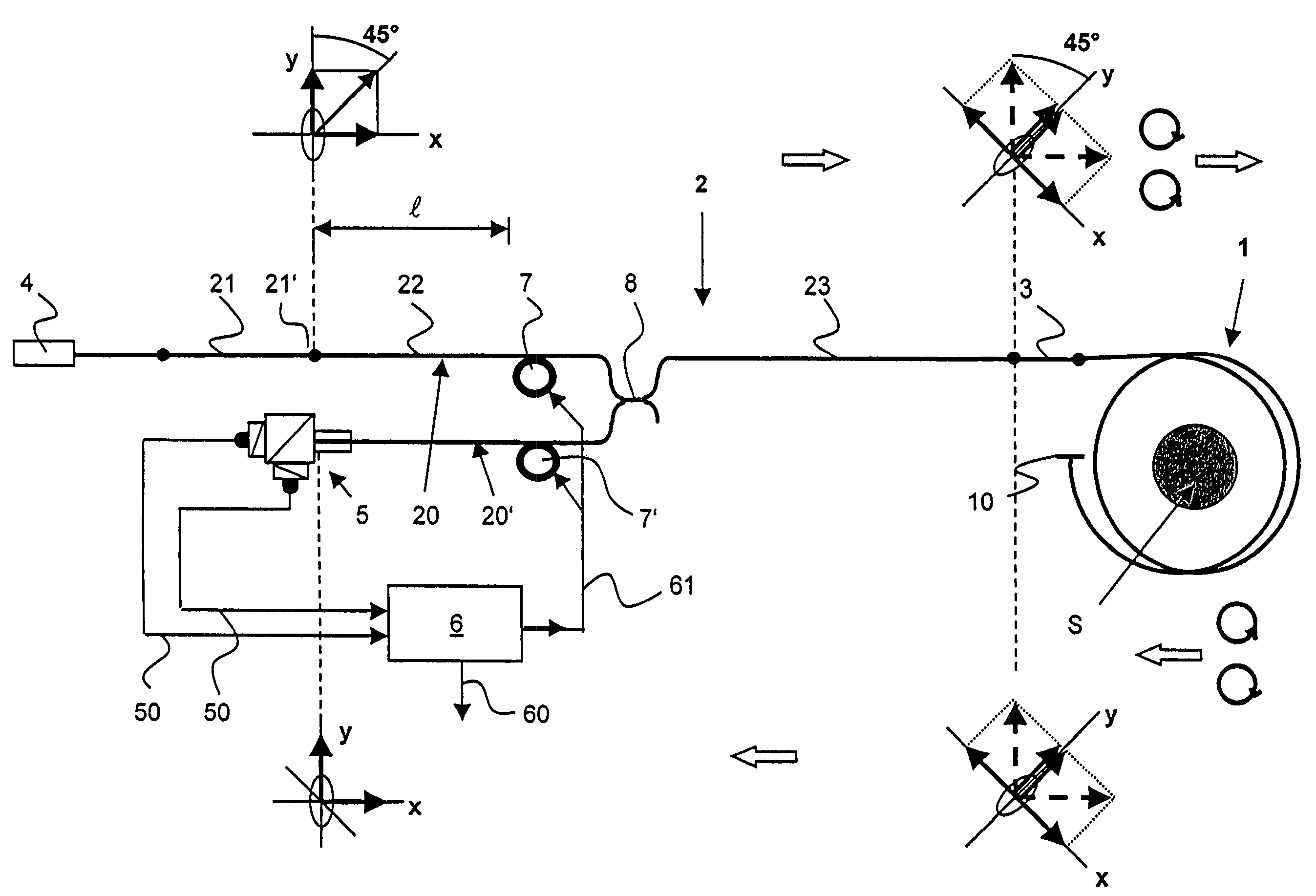
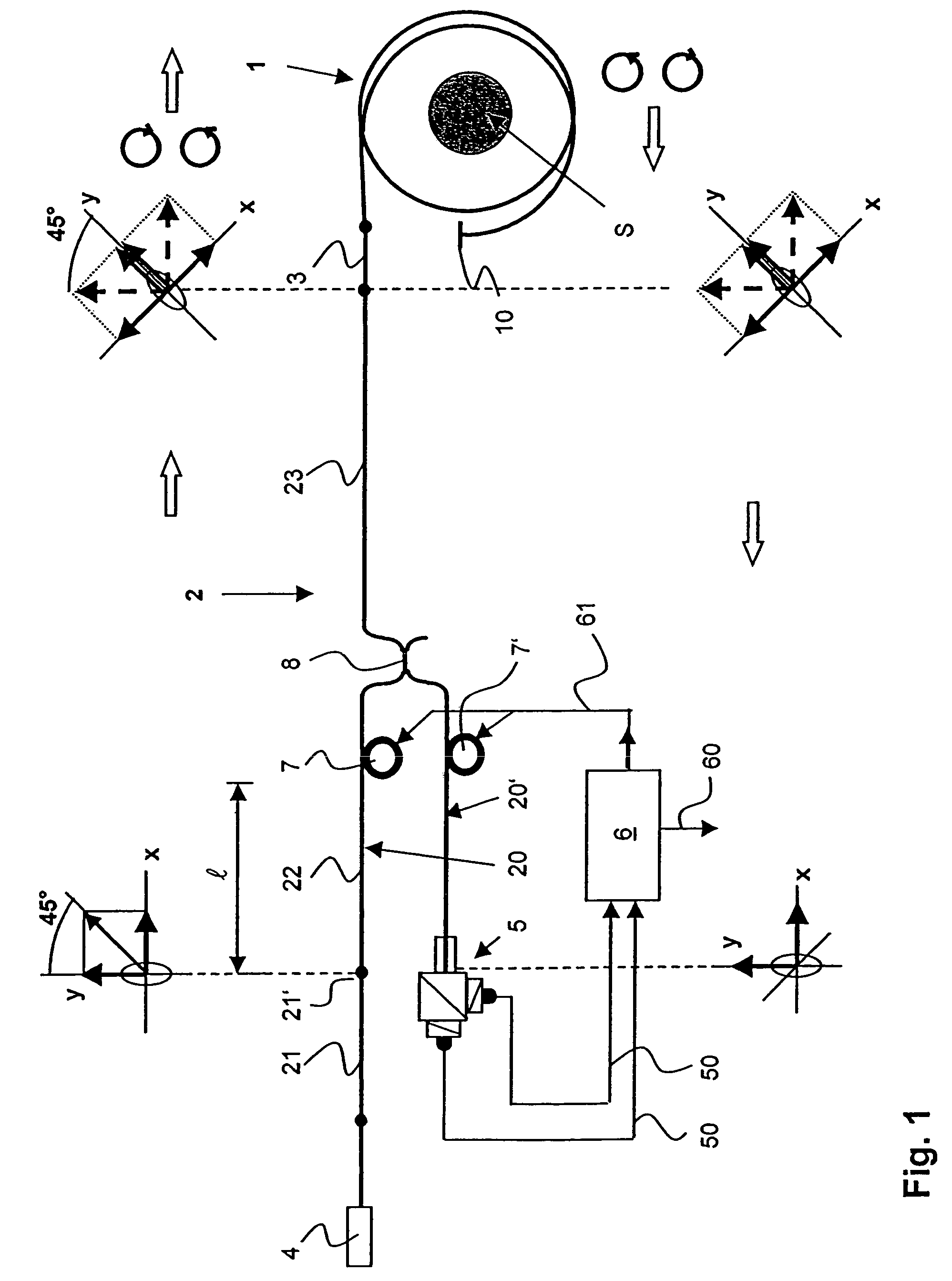
[0021]FIG. 1 shows a fiber-optic current sensor according to the invention, having a reflection interferometer. A sensor fiber 1 is wound in coil form around a current conductor L. It preferably has a round core cross section and is preferably produced from quartz glass. A first end of the sensor fiber 1 is connected to a fiber-optic lead 2. A second end is provided with a reflector 10. The reflector 10 is generally formed by a mirror-coating of the second fiber end. The lead 2 is designed, at least in sections, to be birefringent and therefore, polarization-maintaining. It preferably has an elliptical core cross-section for generating the birefringence. The use of a stress-induced birefringent fiber is possible, however. The lead 2 is connected to the sensor fiber 1 via a phase delay element 3, a λ / 4 phase delay fiber segment preferably being used for this.

[0022]Furthermore, there is a light source 4 present, the light from which is communicated through the fibers. A suitable light...


PUM


Abstract

An optical current sensor having a reflection interferometer (1, 10) has, in its fiber-optic lead (2), a polarization-maintaining first fiber branch (20) for two forward-traveling orthogonally polarized waves and a polarization-maintaining second fiber branch (20′) for two backward-traveling orthogonally polarized waves. In this case, the two fiber branches (20, 20′) are connected to one another via a coupler (8) on the sensor side. The first fiber branch (20) is connected to a light source (4) and the second fiber branch (20′) is connected to the detector (5). A means for phase shifting (7) is funcionally connected to at least one of the fiber branches (20, 20′). It is thus possible to achieve a quasi-static control of the phase shift of the waves, so that less stringent requirements can be made of the means for phase shifting than of the phase modulators that are usually used in current sensors of this type.

Description


Claims


Application Information

Patent Timeline
Owner ABB RES LTD
Why Eureka
Try Eureka