Electrically Tunable Microresonators Using Photoaligned Liquid Crystals

a liquid crystal and photoalignment technology, applied in the field of optical devices, can solve the problems of difficult realization of silicon-based electro-optical devices, inability to readily leverage from the multi-billion-dollar establishment of the silicon microelectronics industry, and inability to easily integrate photonic and optoelectronic devices with mainstream silicon microelectronics, etc., to improve the quality and reliability of switching

Active Publication Date: 2007-11-08
THE HONG KONG UNIV OF SCI & TECH
View PDF8 Cites 59 Cited by
  • Summary
  • Abstract
  • Description
  • Claims
  • Application Information

AI Technical Summary

Benefits of technology

[0023] Producing of highly uniform liquid crystal alignment on the microring resonator, thus improving the quality and reliability of switching.

Problems solved by technology

However, these photonic and optoelectronic devices are not readily compatible with mainstream silicon microelectronics, and thus cannot readily leverage from the multibillion-dollar establishment of the silicon microelectronics industry.
However, realization of silicon-based electro-optical devices can be a challenge as silicon only exhibits weak linear electro-optic effect.
Yet, the tuning range is limited as the refractive index change is only on the order of 10−3, and also the free carriers induce light absorption that causes additional cavity losses.
However, thermal flow in micro-meter-size silicon devices is difficult to control and localize as silicon is a good thermo-conductive material.
Thus, the thermal influence on neighboring devices in a large-scale integration is hard to be totally avoided and thermal-induced cross-talk talk is likely to exist.
Yet such micromechanical tunable microresonator devices have mechanical moving parts that may not be desirable for long-term device reliability.

Method used


Image

  • Electrically Tunable Microresonators Using Photoaligned Liquid Crystals
  • Electrically Tunable Microresonators Using Photoaligned Liquid Crystals
  • Electrically Tunable Microresonators Using Photoaligned Liquid Crystals

Examples


Embodiment Construction

[0047] The numerous innovative teachings of the present application will be described with particular reference to the presently preferred embodiment (by way of example, and not of limitation).

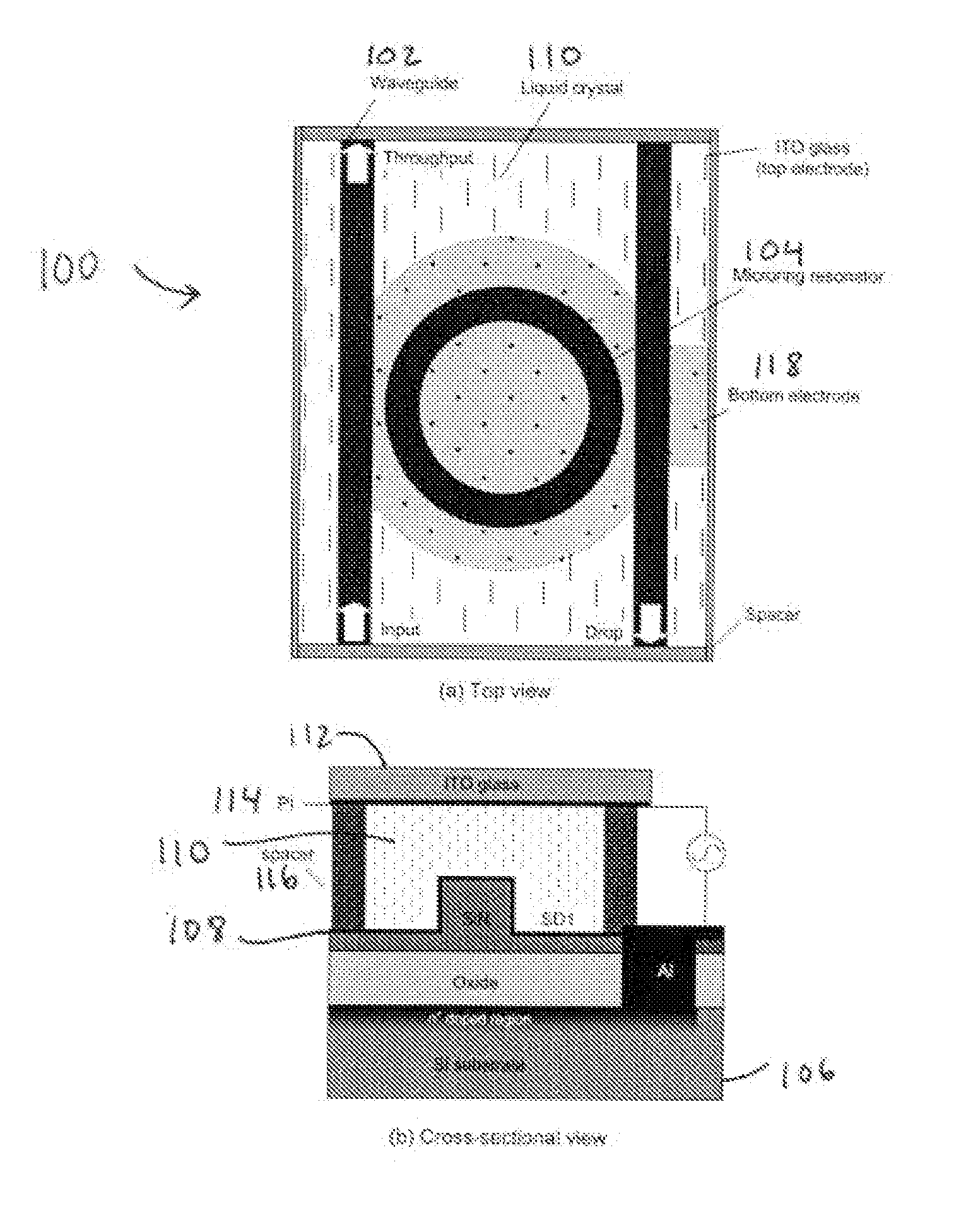
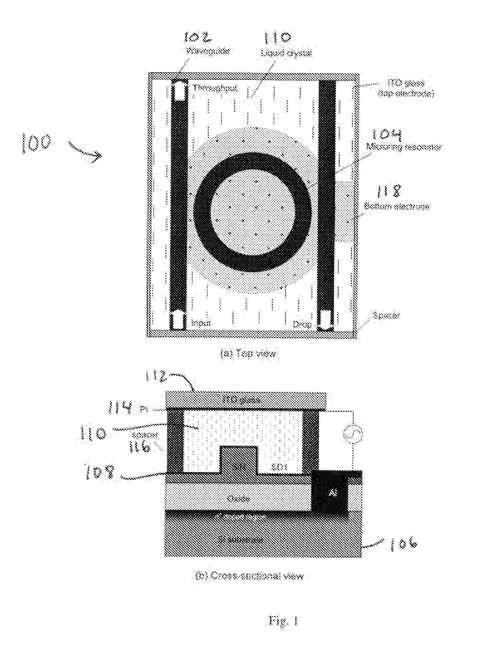
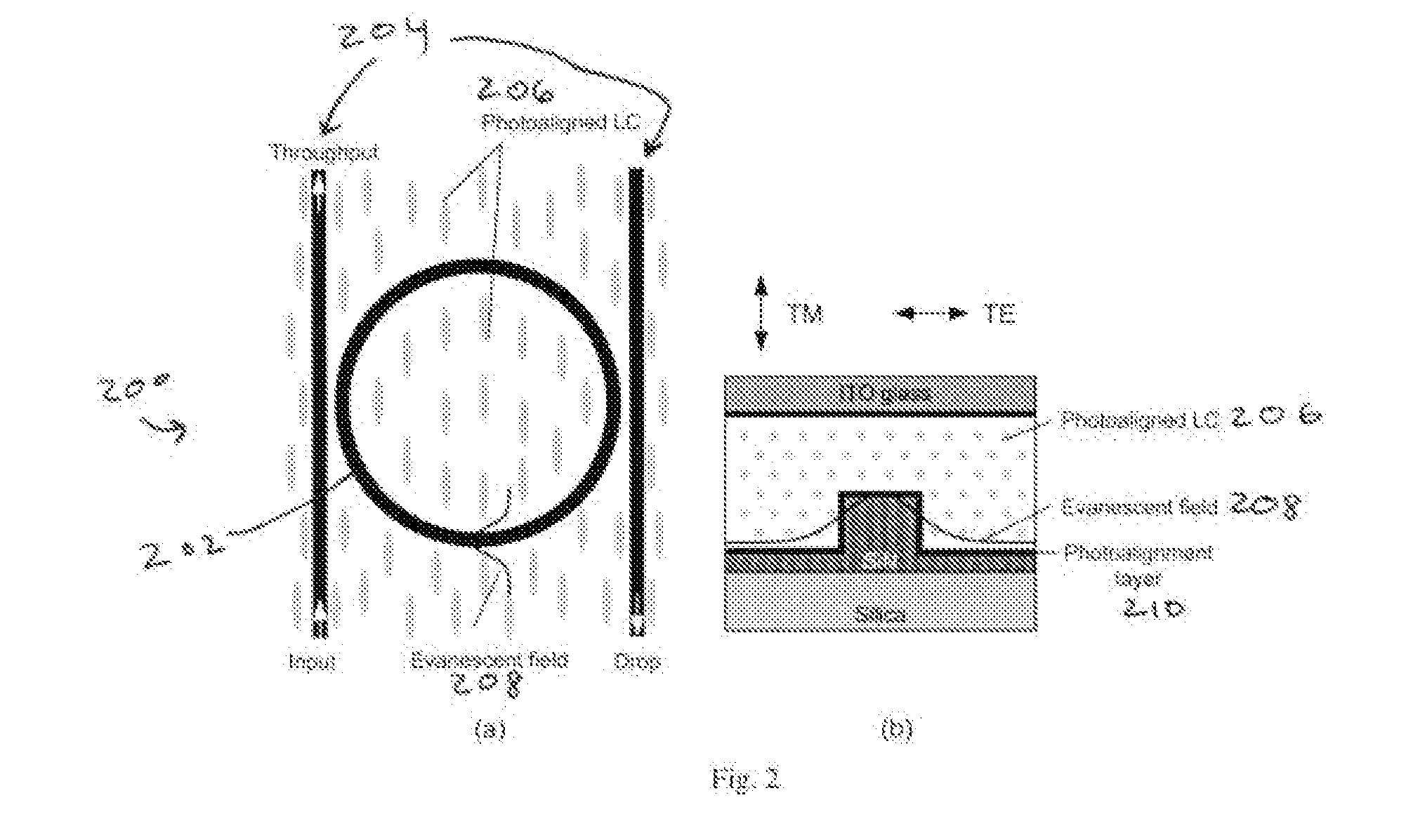
[0048] The present innovations include, in one example embodiment, an electrooptically tunable waveguide coupled microresonator. In preferred embodiments (described more fully below), the innovative device includes a photoalignment layer as part of the cladding, which is in turn covered by a liquid crystal region. Non-flat surfaces, such as the surface of a silicon chip with waveguides and microring resonators described herein, have edge profiles that cause intrinsic alignment of liquid crystal. This alignment causes the LC director to take a fixed position in the region near the evanescent field, or close to the resonator and waveguide (which are formed as relatively tiny surface structures, and thus have edges). The director is held at this position at a certain strength that can be describ...


PUM


Abstract

An electrooptically tunable waveguide-coupled microresonator. In one example embodiment, the switch includes a photoalignment layer that enhances control of liquid crystal alignment in the cladding near the coupling region of the microresonator and waveguide.

Description

CROSS-REFERENCE TO RELATED APPLICATIONS [0001] This application claims priority from U.S. provisional patent application 60 / 794,128 filed on Apr. 24, 2006, which is hereby incorporated by reference.BACKGROUND AND SUMMARY OF THE INVENTION [0002] The present application relates to optical devices, and more particularly to an electrically tunable microresonator using photoaligned liquid crystal as a cladding. DESCRIPTION OF BACKGROUND ART [0003] The present invention relates to the field of electrooptic switches for wavelength-selective routing of waveguided light. [0004] Planar optical microresonators that partially confine light by total internal reflection in micrometer-size dielectric structures on substrates and support sharp optical resonances have long been demonstrated as integrated optic filters, multiplexers, and demultiplexers for wavelength-division-multiplexed (WDM) communications, and as wavelength-agile components for non-communications applications such as biochemical s...

Claims


Application Information

Patent Timeline
Patent Type & Authority Applications(United States)
IPC IPC(8): G02B6/26G02B6/42
CPCG02B6/12007G02F2203/15G02F1/3132G02F1/133788
Inventor CHIGRINOV, VLADIMIR G.ZHOU, LINJIEMURAVSKY, ALEXANDER A.POON, ANDREW WING ON
Owner THE HONG KONG UNIV OF SCI & TECH
Why Eureka
Try Eureka