Current sensor

a current sensor and current sensor technology, applied in the direction of voltage/current isolation, basic electric elements, instruments, etc., can solve the problems of height and circuit board area, device size is often undetected,

Active Publication Date: 2006-07-11
ALLEGRO MICROSYSTEMS INC
View PDF22 Cites 106 Cited by
  • Summary
  • Abstract
  • Description
  • Claims
  • Application Information

AI Technical Summary

Benefits of technology

[0009]In accordance with the present invention, an integrated circuit includes a lead frame portion having a plurality of leads and a current conductor portion comprising at least two of the plurality of leads. The integrated circuit also includes a substrate having first and second opposing surfaces. The first surface is proximate to the current conductor portion and the second surface is distal from the current conductor portion. The integrated circuit also includes one or more magnetic field sensing elements disposed proximate to the current conductor portion. The integrated circuit also includes a current sensing circuit disposed on the first surface of the substrate and coupled to the one or more magnetic field sensing elements. The current sensing circuit is adapted to provide an output signal indicative of a current flowing through the current conductor portion. The integrated circuit also includes an overcurrent circuit disposed on the first surface of the substrate. The overcurrent circuit is adapted to sense a voltage drop associated with a current and further adapted to provide an output signal in response to the voltage drop. The output signal from the overcurrent circuit is indicative of the current sensed by the overcurrent circuit being above a predetermined current.
[0010]In accordance w

Problems solved by technology

Such devices tend to be undesirably large, bo

Method used


Image

  • Current sensor
  • Current sensor
  • Current sensor

Examples


Embodiment Construction

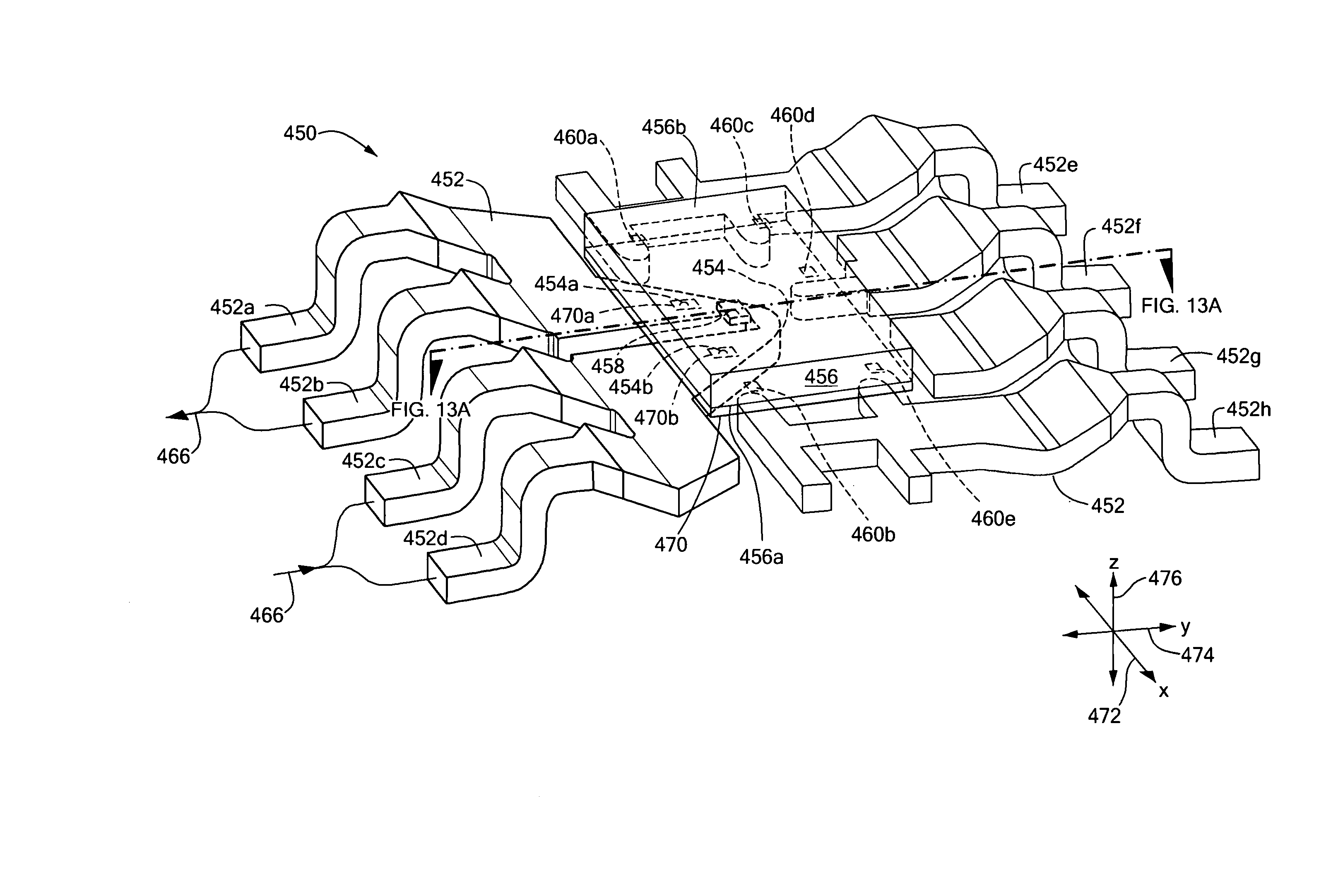
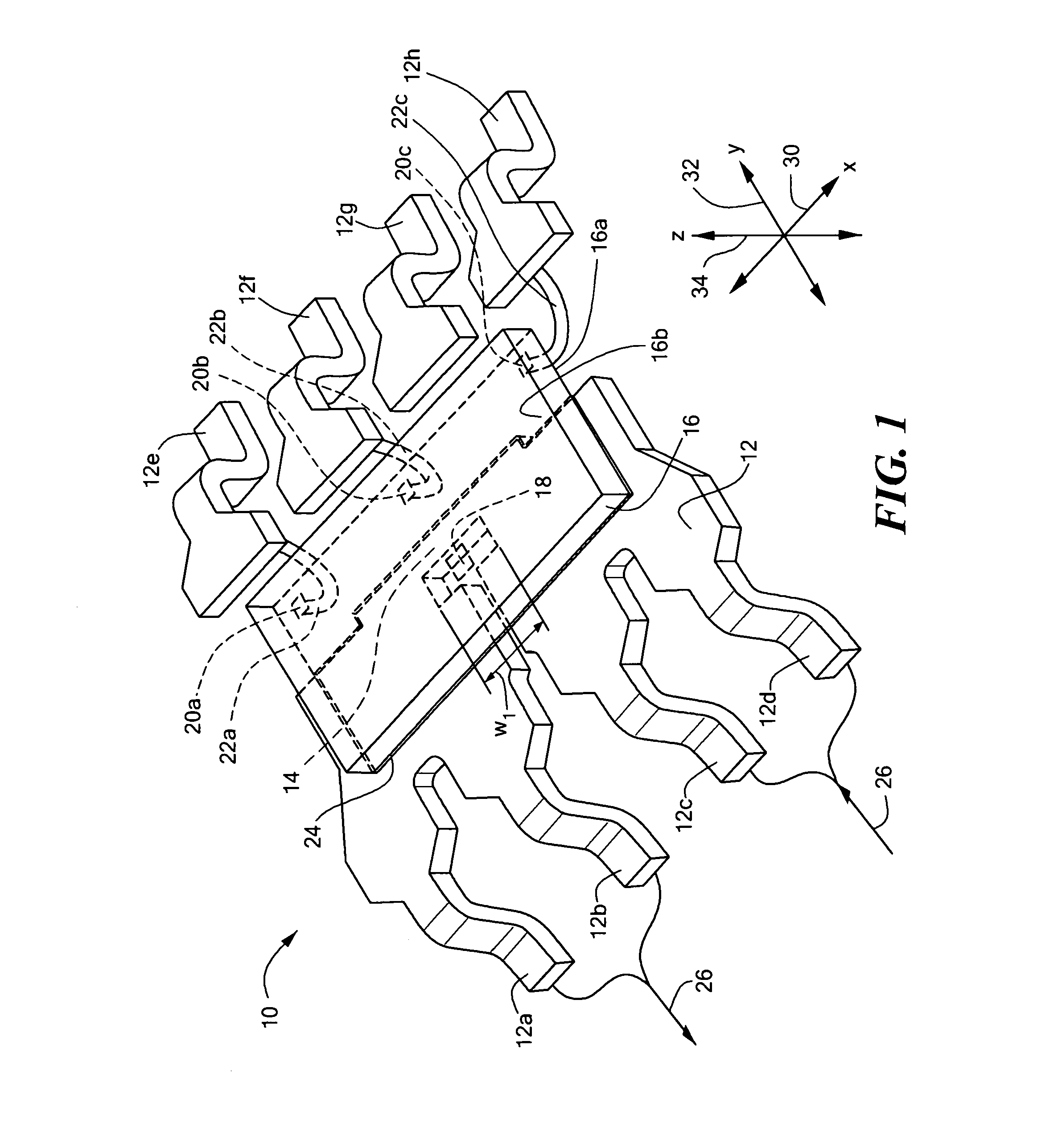
[0032]Referring to FIG. 1, an exemplary current sensor 10 in accordance with the present invention includes a lead frame 12 having a plurality of leads 12a–12h. The leads 12a and 12b are coupled to the leads 12c and 12d to form a current path, or current conductor with a narrow portion 14 having a width w1. The current sensor 10 also includes a substrate 16 having a first surface 16a and a second, opposing surface 16b. The substrate 16 has a magnetic field transducer 18 which, in some embodiments, can be a Hall effect element 18, diffused into the first surface 16a, or otherwise disposed on the first surface 16a. The substrate 16 can be comprised of a semiconductor material, e.g., silicon, or, in an alternate embodiment, the substrate 16 can be comprised of an insulating material.

[0033]The substrate 16 is disposed above the lead frame 12 so that the first surface 16a is proximate to the current conductor portion 14 and the second surface 16b is distal from the current conductor port...


PUM


Abstract

An integrated circuit current sensor includes a lead frame having at least two leads coupled to provide a current conductor portion, and a substrate having a first surface in which is disposed one or more magnetic field sensing elements, with the first surface being proximate to the current conductor portion and a second surface distal from the current conductor portion. In one particular embodiment, the substrate is disposed having the first surface of the substrate above the current conductor portion and the second surface of the substrate above the first surface. In this particular embodiment, the substrate is oriented upside-down in the integrated circuit in a flip-chap arrangement. The integrated circuit includes an overcurrent circuit responsive to a voltage drop generated by a current.

Description

CROSS-REFERENCE TO RELATED APPLICATIONS[0001]This application is a Continuation-in-Part application of and claims the benefit under 35 U.S.C. §120 of U.S. application Ser. No. 11 / 144,970 filed on Jun. 3, 2005, which is a Continuation-in-Part application of and claims the benefit under 35 U.S.C. §120 of U.S. application Ser. No. 11 / 140,250 filed on May 27, 2005 now U.S. Pat. No. 6,995,315, which is a Continuation-in-Part application of and claims the benefit under 35 U.S.C. §120 of U.S. application Ser. No. 10 / 649,450 filed on Aug. 26, 2003, which applications are incorporated herein by reference in their entirety.STATEMENT REGARDING FEDERALLY SPONSORED RESEARCH[0002]Not Applicable.FIELD OF THE INVENTION[0003]This invention relates generally to electrical current sensors, and more particularly to a miniaturized current sensor in an integrated circuit package.BACKGROUND OF THE INVENTION[0004]As is known in the art, one type of conventional current sensor uses a magnetic field transduc...

Claims


Application Information

Patent Timeline
IPC IPC(8): G01R33/00
CPCG01R1/36G01R15/202H01L24/34G01R15/207H01L2224/48091H01L2224/48247H01L2924/1306H01L2924/00014H01L2924/00H01L2924/01322H01L2224/40095H01L2924/181H01L2224/40245H01L24/40H01L2924/14H01L2224/73221H01L2224/84801H01L2224/37147H01L24/37H01L2224/8485H01L24/84H01L2924/00012
Inventor MANGTANI, VIJAYDOOGUE, MICHAEL C.TAYLOR, WILLIAM P.
Owner ALLEGRO MICROSYSTEMS INC
Why Eureka
Try Eureka