Signal isolators using micro-transformers

a technology of signal isolators and transformers, applied in the field of digital signal isolators, can solve the problems of not working well at high frequencies, limited isolation levels, and conductive shields which provide a significant degree of isolation are not sufficiently transparent for use in this application

Active Publication Date: 2006-07-11
ANALOG DEVICES INC
View PDF77 Cites 284 Cited by
  • Summary
  • Abstract
  • Description
  • Claims
  • Application Information

AI Technical Summary

Problems solved by technology

Optical isolators, which are probably the most prevalent, present certain well-known limitations Among other limitations, they require significant space on a card or circuit board, they draw a large current, they do not operate well at high frequencies, and they are very inefficient.
They also provide somewhat limited levels of isolation.
However, a conductive shield which provides a significant degree of isolation is not sufficiently transparent for use in this application.
This current potentially can damage the receiving circuit and can trigger a faulty detection.
The patent also mentions, without elaboration, that a transformer with a short R / L time constant can provide an isolation barrier, but such a differential approach is nonetheless undesirable because any mismatch in the non-magnetic (i.e., capacitive) coupling of the windings would cause a common-mode signal to appear as a difference signal.
Transformer cost and size may also be a negative factor, and transformers having cores of magnetic materials such as ferrites become inefficient at high frequencies and are not useful for coupling high-speed digital signals.

Method used


Image

  • Signal isolators using micro-transformers
  • Signal isolators using micro-transformers
  • Signal isolators using micro-transformers

Examples


Embodiment Construction

[0038]This invention is not limited in its application to the details of construction and the arrangement of components set forth in the following description or illustrated in the drawings. The invention is capable of other embodiments and of being practiced or of being carried out in various ways. Also, the phraseology and terminology used herein is for the purpose of description and should not be regarded as limiting. The use of “including,”“comprising,” or “having,”“containing”, “involving”, and variations thereof herein, is meant to encompass the items listed thereafter and equivalents thereof as well as additional items.

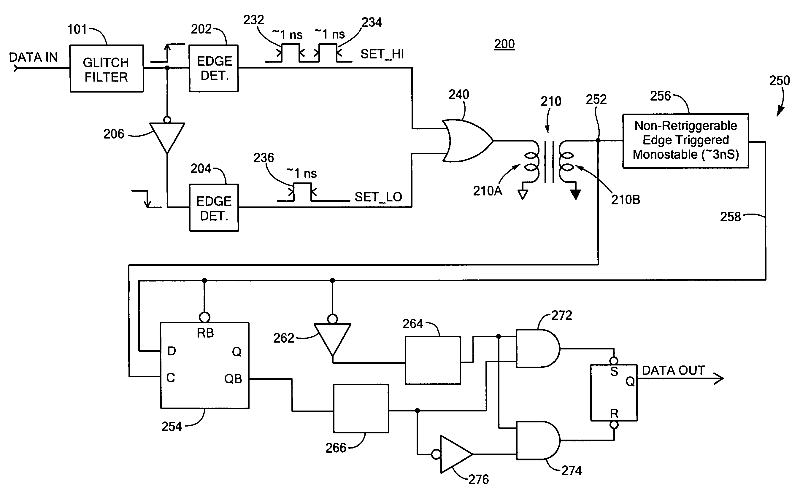
[0039]Micro-transformer based digital isolators have been developed in recent years by applicants and their colleagues. This genus of digital isolators shows dramatic improvements over traditional opto-isolators in terms of speed, power, edge symmetry and cost. The transmission methods employed in these micro-transformer based digital isolators fall into two ma...


PUM

PropertyMeasurementUnit
timeaaaaaaaaaa
electricallyaaaaaaaaaa
frequencyaaaaaaaaaa

Abstract

A logic signal isolator comprising a transformer having a primary winding and a secondary winding; a transmitter circuit which drives said primary winding in response to a received logic signal, such that in response to a first type of edge in the logic signal, a signal of a first predetermined type is supplied to the primary winding and in response to a second type of edge in the logic signal, a signal of a second predetermined type is supplied to said primary winding, the primary winding and the transmitter being referenced to a first ground; and the secondary winding being referenced to a second ground which is galvanically isolated from the first ground and said secondary winding supplying to a receiver circuit signals received in correspondence to the signals provided to the primary winding, the receiver reconstructing the received logic signal from the received signals.

Description

CROSS-REFERENCE TO RELATED APPLICATIONS[0001]This application claims priority under 35 U.S.C. § 119(e) to U.S. Provisional Application Ser. No. 60 / 466,602 entitled “BI-DIRECTIONAL SIGNAL ISOLATORS USING MICRO-TRANSFORMERS,” filed on Apr. 30, 2003, which is herein incorporated by reference in its entirety.FIELD OF THE INVENTION[0002]This invention relates to signal isolators, more particularly digital signal isolators, and even more particularly to digital signal isolators employing transformers to establish an isolation barrier.BACKGROUND OF THE INVENTION[0003]In a variety of environments, signals must be transmitted between diverse sources and circuitry using those signals, while maintaining electrical (i.e., galvanic) isolation between the sources and the using circuitry. Isolation may be needed, for example, between microcontrollers, on the one hand, and devices or transducers which use microcontroller output signals, on the other hand. Electrical isolation is intended, inter ali...

Claims


Application Information

Patent Timeline
Patent Type & Authority Patents(United States)
IPC IPC(8): H03K17/16H01L25/00H01F17/00H01F19/08H01L23/522H03K5/1252
CPCH01F17/0006H03K5/1252H04L25/0266H01F19/08H01L2924/13091H01F2017/0093H01F2019/085H01F2038/143H01L23/5227H01L23/60H01L23/645H01L2224/48091H01L2224/48137H01L2924/00014H01L2224/05554H01L2924/00H01L2224/45099
Inventor CHEN, BAOXINGHAIGH, GEOFFREY
Owner ANALOG DEVICES INC
Why Eureka
Try Eureka