Range finder and method

a three-dimensional image and range finder technology, applied in the field of three-dimensional image pickup art, can solve the problems of large calculation amount of restoring the code, coding is broken, and it is difficult to easily pick up an imag

Inactive Publication Date: 2006-07-11
FUJIFILM BUSINESS INNOVATION CORP
View PDF14 Cites 21 Cited by
  • Summary
  • Abstract
  • Description
  • Claims
  • Application Information

AI Technical Summary

Benefits of technology

[0049]In the configuration, it is not necessary to place a half mirror or a beam splitter between the projector and the image pickup device (first camera) of the projection system as described above, so that image de

Problems solved by technology

Therefore, even if the apparatus itself becomes simple, it is difficult to easily pick up an image.
However, in the color coding, codes are restored from the coding pattern list and thus there is a problem of large calculation amount of restoring the codes.
However, in the above described system, coding is broken depending on the object to be measured and it may be made impossible to correctly relate codes to each other.
It becomes difficult to relate because of change in the projected pattern and photographed pattern row depending on the shape of the object, the reflection factor of the object, etc.
In the space coding method, a two-dimensional pattern is used to decrease the possibility of the error described above, but the same error will occur depending on the object on principle.
That is, the shadow areas are areas blocked by the plate that light does not reach, and cannot be measured according to the system.
At this time, the projection pattern is changed by the effects of brightness information, material

Method used


Image

  • Range finder and method
  • Range finder and method
  • Range finder and method

Examples


Embodiment Construction

[0085]Referring now to the accompanying drawings, there is shown a preferred embodiment of the invention.

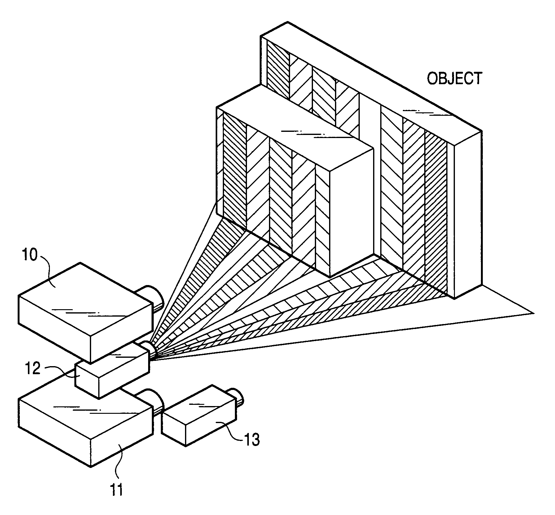
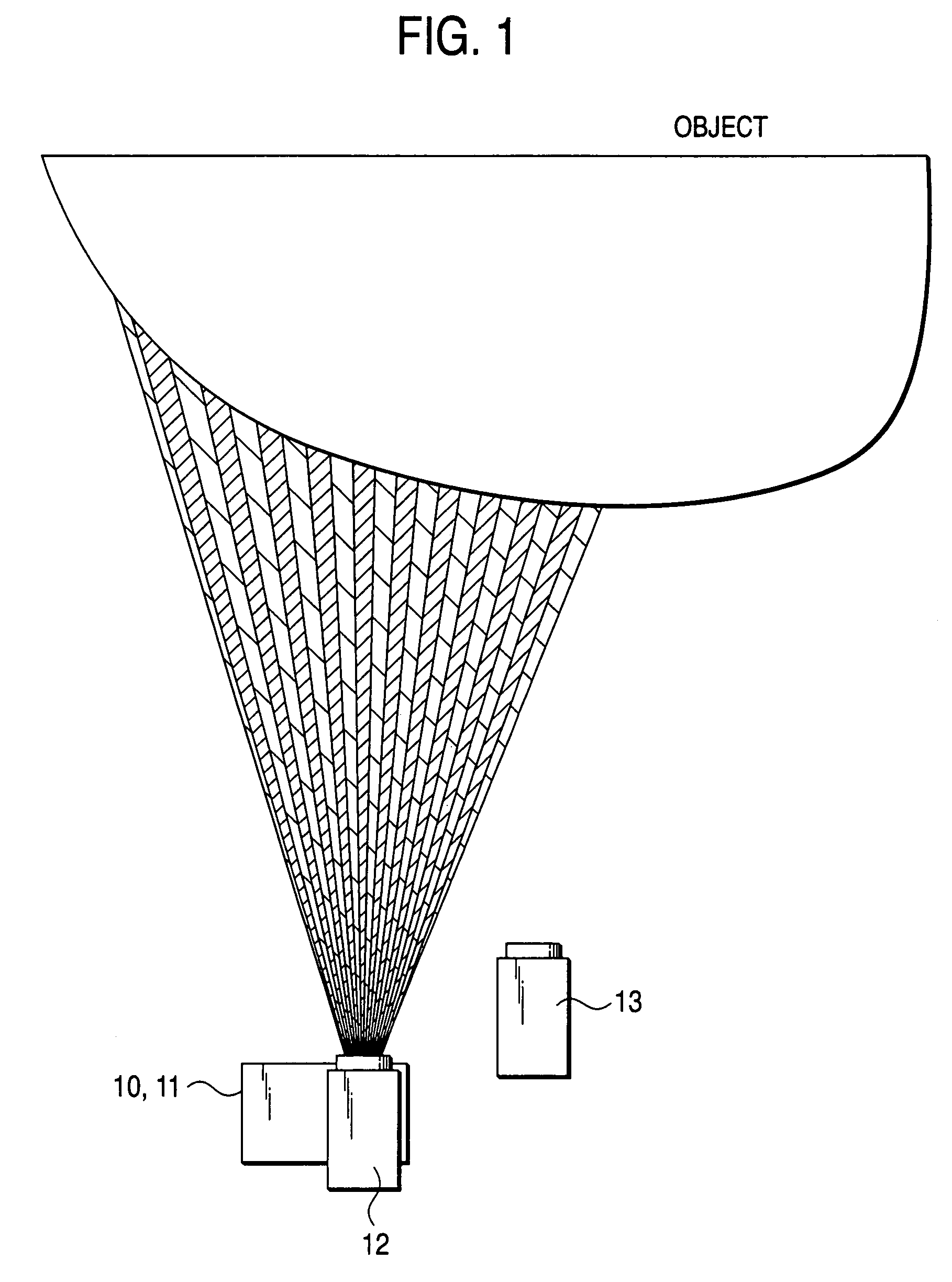
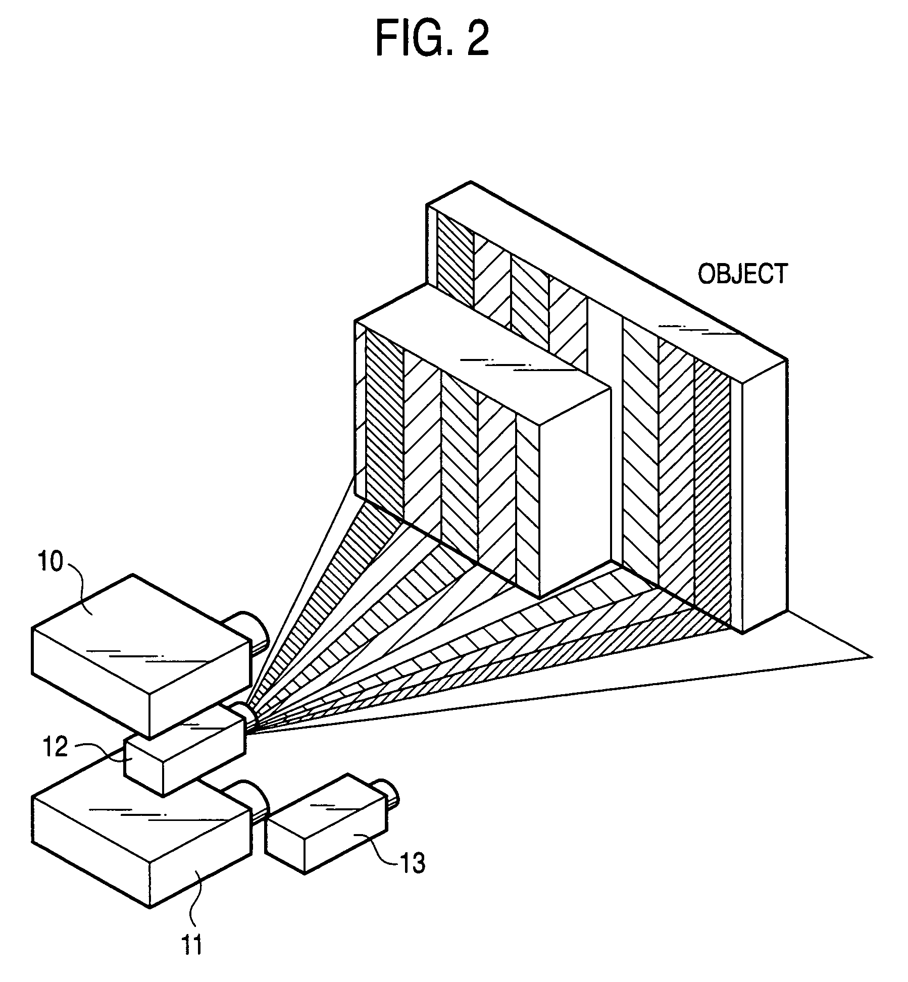
[0086]FIG. 1 is a top view of a range finder according to an embodiment of the invention. FIG. 2 is a drawing of viewing the range finder from the slanting top thereof. In the embodiment, two pattern projection apparatus (also called projectors) are used. As the pattern projection apparatus, for example, commercially available projectors for projecting an image onto a screen can be used.

[0087]In the embodiment, generation of a coded stripe pattern, monitor of a coded stripe pattern, re-coding based on the monitor, and triangulation are similar to those in the related arts previously described with reference to FIGS. 15 to 26 and therefore will not be discussed again.

[0088]In FIGS. 1 and 2, the range finder includes two pattern projection apparatus (projectors) 10 and 11, an image pickup apparatus (camera 1) 12, and an image pickup apparatus (camera 2) 13 for triangulation. The im...


PUM


Abstract

Pattern projection apparatuses are placed on each other in a stack manner in a stripe pattern direction for projecting the same patterns. An image pickup apparatus (camera 1) is placed between the pattern projection apparatuses. The optical axes of the pattern projection apparatuses and the image pickup apparatus are aligned on the same plane parallel with the stripe pattern direction. On the plane, the principal points also become the same. An image of a stripe pattern is picked up directly by the image pickup apparatus without the intervention of a half mirror, etc., and is recoded. An image of the recoded stripe pattern is picked up by an image pickup apparatus (camera 2) and is decoded and the range of an object is measured by triangulation based on image correspondence points.

Description

[0001]This is a continuation-in-part application of application Ser. No. 10 / 373,761 filed Feb. 27, 2003.[0002]The present disclosure relates to the subject matter contained in Japanese Patent Application No. 2002-248034 filed on Aug. 28, 2002 and Japanese Patent Application No. 2003-299505 filed on Aug. 25, 2003, which are incorporated herein by reference in its entirety.BACKGROUND OF THE INVENTION[0003]1. Field of the Invention[0004]The invention relates to a three-dimensional image pickup art based on a triangulation technique for picking up a pattern projection image provided by applying pattern light to a measurement object from different directions by one or a plurality of image pickup device and obtaining a range data based on pattern change.[0005]2. Description of the Related Art[0006]As a technique of acquiring a three-dimensional shape, active vision and passive vision are available. The active vision includes (1) a technique of emitting laser light or a ultrasonic wave, me...

Claims


Application Information

Patent Timeline
IPC IPC(8): G01C3/14G01C3/00G01C3/08G01C11/06G01S17/42G01S17/89G06T7/00H04N13/00
CPCG01C3/08G01C11/06G01S17/42H04N13/026G06T7/0057G06T7/0075H04N13/0253G01S17/89G06T7/521G06T7/593H04N13/254H04N13/261
Inventor ABE, TSUTOMU
Owner FUJIFILM BUSINESS INNOVATION CORP
Why Eureka
Try Eureka