

Communication device for selecting route of packet
- Summary
- Abstract
- Description
- Claims
- Application Information
AI Technical Summary
Benefits of technology
Problems solved by technology
Method used
Image

Examples
second embodiment
[0094]Next, the communication device in a second embodiment of the present invention will be described. The second embodiment is substantially the same as the first embodiment, except for the construction of the inputted packet processor, and therefore the discussion will be focused on the inputted packet processor.
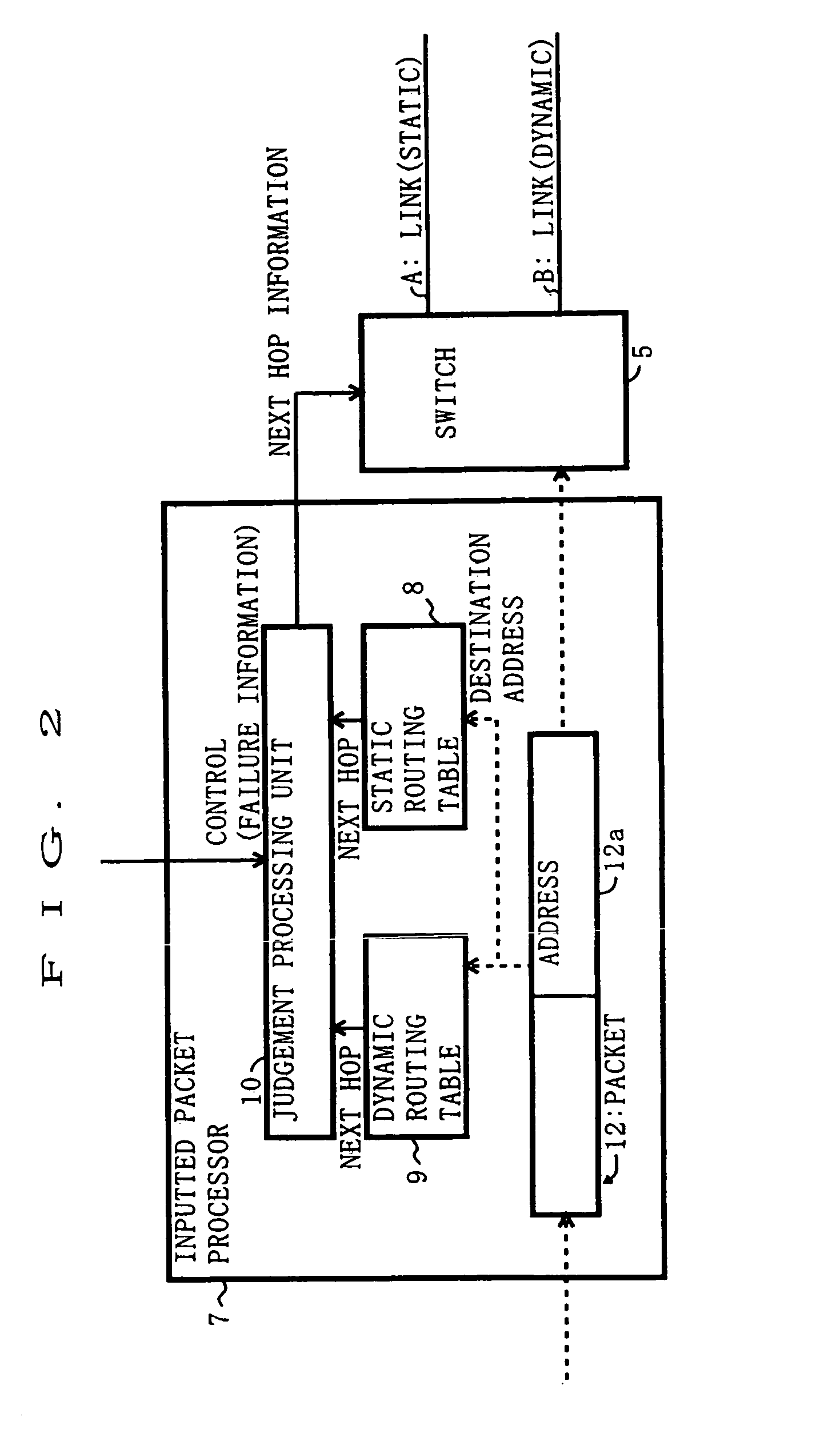
[0095]FIG. 2 is a diagram showing construction of an inputted packet processor 7 provided in the communication device in the second embodiment. The communication device in the second embodiment receives a packet 12. In the inputted packet processor 7, a destination address 12a contained in the packet 12 is inputted, as a common search key, to a static routing table 8 and a dynamic routing table 9 as well.
[0096]Then, each of the routing tables 8 and 9 functions to input a piece of next hop information corresponding to the inputted destination address, to the judgement processing unit 4. Excluding the points described above, the construction and functions of the inputted pa...
third embodiment
[0098]Next, the communication device in a third embodiment of the present invention will be discussed. The third embodiment is substantially the same as the first embodiment, except for the construction of the inputted packet processor, and therefore the discussion will be focused on the inputted packet processor.
[0099]As one category of static routing, a method of adding information for actualizing a virtual circuit into IP datagram (IP packet) may be considered other than the method of directly describing the entry in the routing table.
[0100]The virtual circuit is defined as a technology that has been used in the asynchronous transfer mode (ATM) etc, wherein two points, i.e., a start point and an end point, are connected by the virtual circuit, identification information of a route to the end point is added into the data transferred between those two points, and a node existing on the virtual circuit forwards the data to the route (leading to the end point) based on the identifica...
fourth embodiment
[0111]Next, the communication device in a fourth embodiment of the present invention will be discussed. The fourth embodiment is substantially the same as the third embodiment, except for the construction of the inputted packet processor, and therefore the discussion will be focused on the inputted packet processor.
[0112]FIG. 4 is a diagram showing construction of an inputted packet processor 19 provided in the communication device in the fourth embodiment. The inputted packet processor 19 reflects the policy in the network by MPLS-based static routing as one of the virtual circuit technologies.
[0113]A packet 24 is received (inputted to the inputted packet processor 19) by the communication device in the fourth embodiment, contains labels 24a, 24b (corresponding to plural pieces of virtual circuit information) used as pieces of route identification information when selecting a route (label switching) in MPLS, and a destination address 24c of the packet 24.
[0114]The labels 24a, 24b a...
PUM
 Abstract
Description
Claims
Application Information