X-ray apparatus with dual monochromators

a monochromator and x-ray technology, applied in the field of analytical instruments, can solve problems such as the zero angle of the wafer as it rotates

Active Publication Date: 2006-07-11
BRUKER TECH LTD
View PDF36 Cites 62 Cited by
  • Summary
  • Abstract
  • Description
  • Claims
  • Application Information

AI Technical Summary

Benefits of technology

[0013]The multiple independent measurements, and the increased irradiating power, substantially increase an overall signal-to-noise ratio (SNR) for the system. In addition to improving the overall SNR, using a plurality of irradiating X-ray beams following different beam paths enables random large signal excursions from one of the beams to be rejected. Furthermore, in the case of wafer inspection, the different incoming beam directions of the different paths facilitate accurate determination of the zero angle at the irradiated region.
[0014]The X-ray beams are generated from a single anode in a single X-ray tube, the single anode effectively acting as an X-ray point source. Using a single X-ray tube to produce multiple X-ray beams reduces both the cost and the size of the apparatus, compared to prior art multiple-beam systems.
[0015]In an exemplary embodiment, there are two crystal monochromators which are each formed as doubly curved crystals (DCCs), each of the crystals being curved to have substantially similar radii of curvature. The geometry of the paths of the beams reflected by the DCCs enables the latter to be arranged on a circle orthogonal to a line between the X-ray source and the single region, the circle being centered on the line. Such an arrangement may be implemented without complicated alignment.

Problems solved by technology

Furthermore, the chuck may have imperfections, such as a slight bend in its axis, that cause deviations in the zero angle of the wafer as it rotates.

Method used


Image

  • X-ray apparatus with dual monochromators
  • X-ray apparatus with dual monochromators
  • X-ray apparatus with dual monochromators

Examples


Embodiment Construction

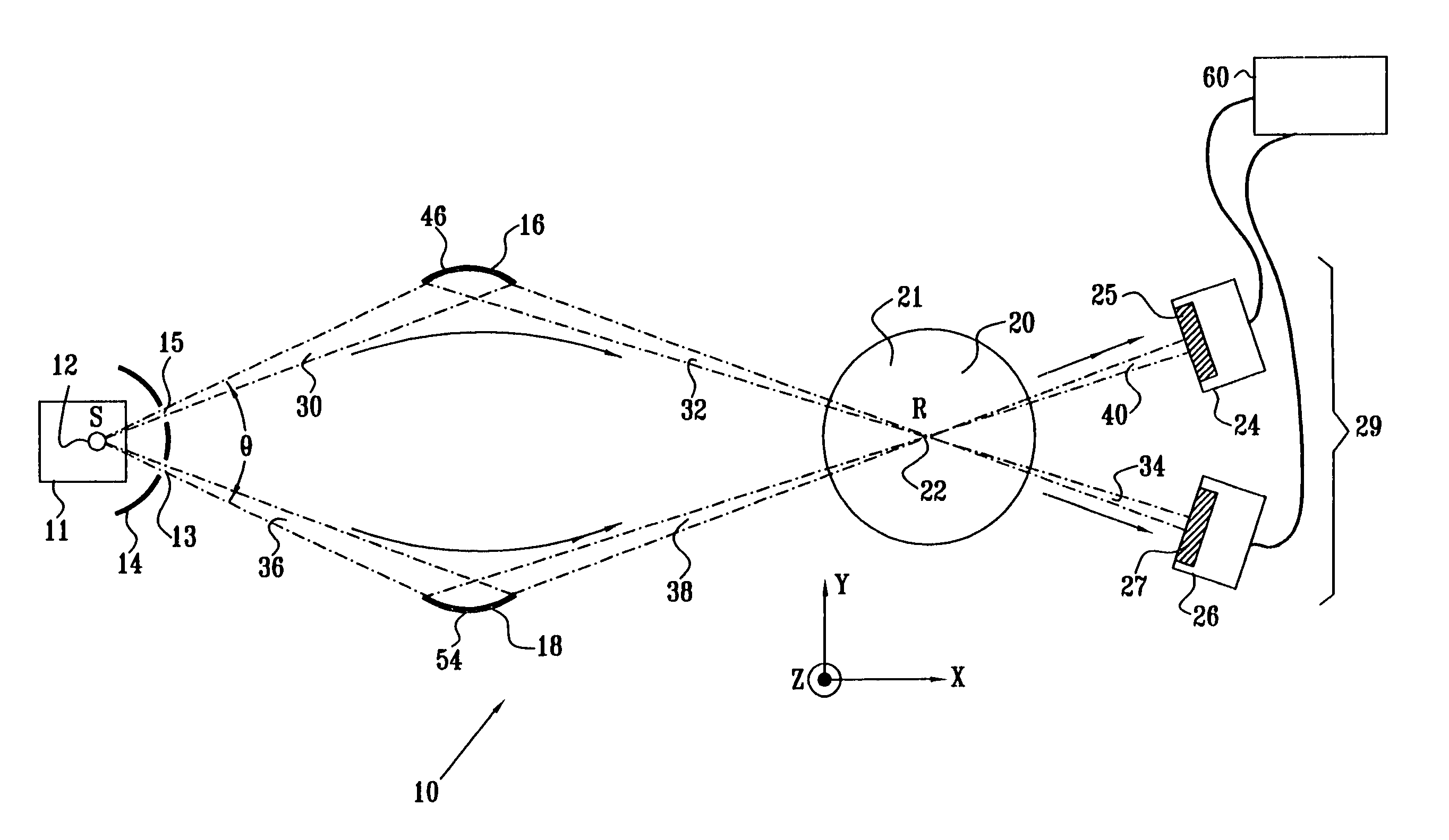
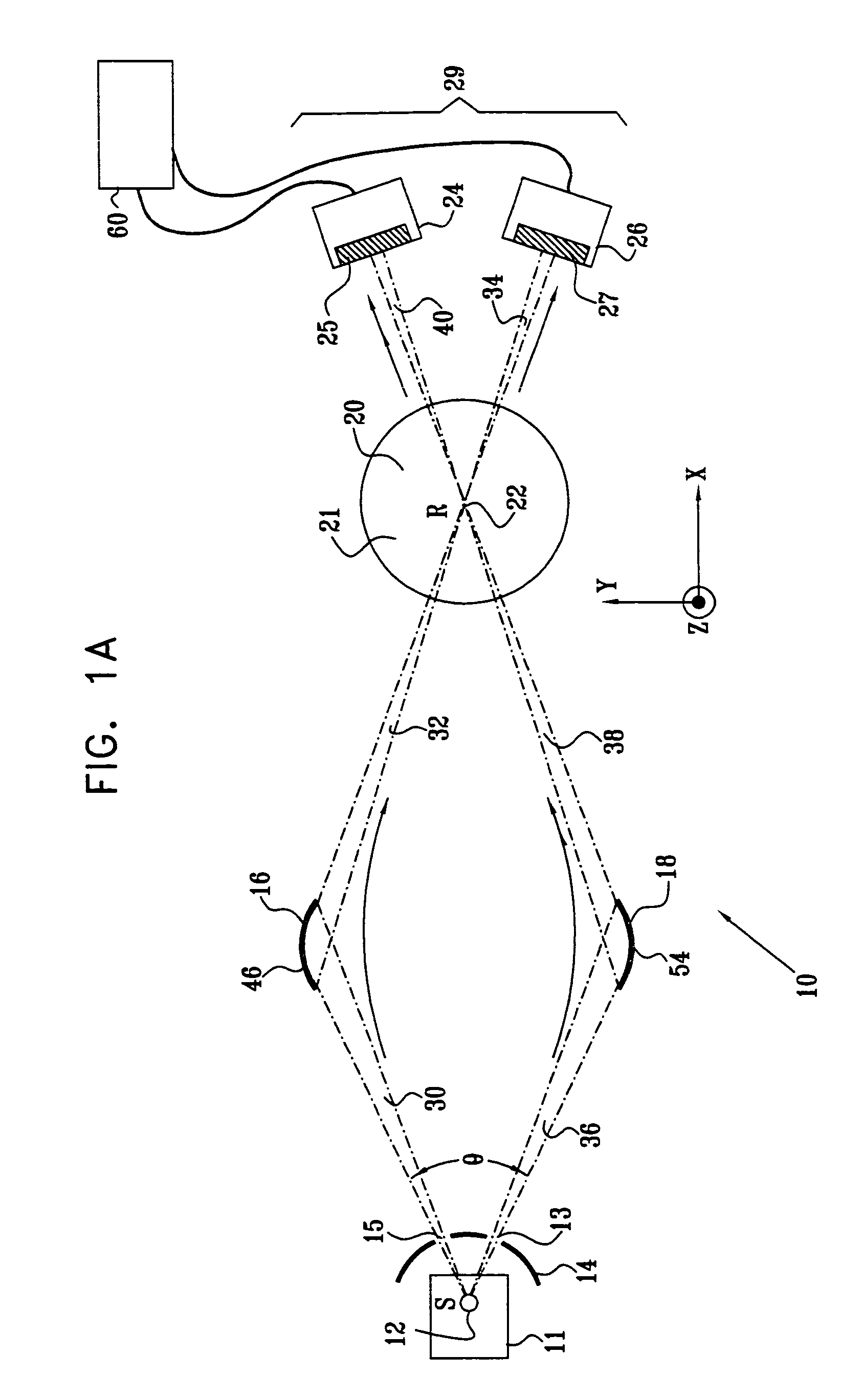
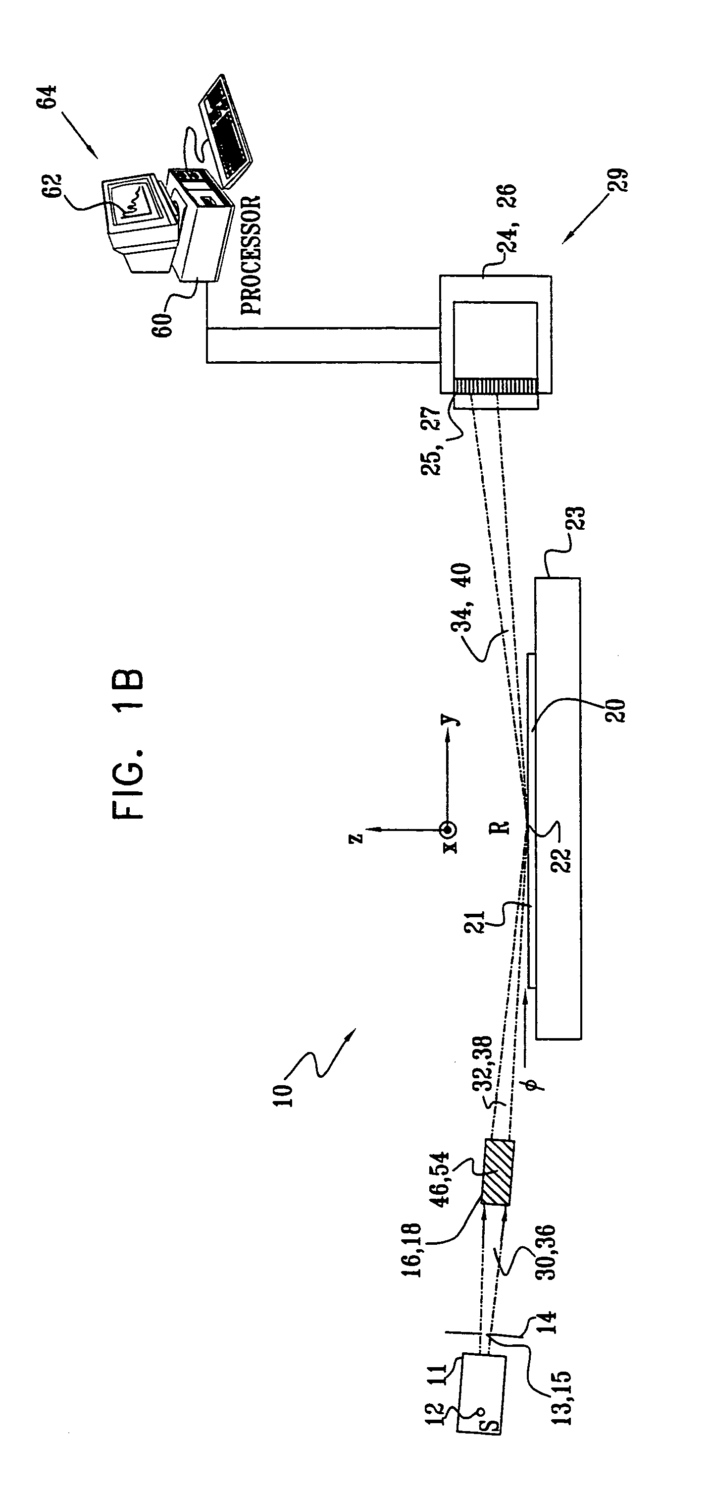
[0052]Reference is now made to FIG. 1A and FIG. 1B, which are schematic top and side views of an X-ray apparatus 10, according to an embodiment of the present invention. Like numerals in FIGS. 1A and 1B identify like elements of the apparatus. The description herein is directed, by way of example, to X-ray examination, typically comprising X-ray reflectometry (XRR) and / or diffractometry (XRD), of a region on a surface of a semiconductor wafer. The examination is typically to determine a property, such as a thickness, a density and / or a surface roughness, of a thin surface layer of the wafer. It will be understood, however, that the principles of the present invention may be applied to irradiation of substantially any type of region to which the irradiating X-rays can be directed. Such regions include the interior and / or the surface of gases, liquids and colloids, as well as the interior and / or the surface of solids.

[0053]A single X-ray tube 11, such as an XTF 5011 produced by Oxford...


PUM

PropertyMeasurementUnit
zero angleaaaaaaaaaa
diameteraaaaaaaaaa
angles of divergenceaaaaaaaaaa

Abstract

X-ray apparatus, consisting of a single X-ray tube which is adapted to generate X-rays and a first optic which is adapted to focus a first portion of the X-rays onto a region of a sample via a first beam path, thereby generating first scattered X-rays from the region. The apparatus also includes a second optic which is adapted to focus a second portion of the X-rays onto the region of the sample via a second beam path, different from the first beam path, thereby generating second scattered X-rays from the region. A detector assembly simultaneously collects the first and the second scattered X-rays.

Description

FIELD OF THE INVENTION[0001]The present invention relates generally to analytic instruments, and particularly to analytic instruments and methods using X-ray scattering.BACKGROUND OF THE INVENTION[0002]X-ray reflectometry (XRR) is a well-known technique for measuring the thickness, density and surface quality of thin film layers deposited on a substrate. Such reflectometers typically operate by irradiating a sample with a beam of X-rays at grazing incidence, i.e., at a small angle relative to the surface of the sample, in the vicinity of the total external reflection angle of the sample material. Measurement of the X-ray intensity reflected from the sample as a function of angle gives a pattern of interference fringes, which is analyzed to determine the properties of the film layers responsible for creating the fringe pattern. The X-ray intensity measurements are commonly made using a position-sensitive detector.[0003]Various types of position-sensitive X-ray detectors are known in ...

Claims


Application Information

Patent Timeline
Patent Type & Authority Patents(United States)
IPC IPC(8): G01N23/20
CPCG01N23/201G01N23/207
Inventor YOKHIN, BORIS
Owner BRUKER TECH LTD
Why Eureka
Try Eureka