Shoestring tying apparatus

a technology of shoestring ties and tying parts, which is applied in the direction of snap fasteners, shoe lace fastenings, buckles, etc., can solve the problems of troublesome user, difficult to securely fasten the fastening member b>22/b> by rotating the aforementioned rotational cap b>24/b>, etc., to improve the portability and appearance of the shoestring ties and improve the appearance. , the effect o

Inactive Publication Date: 2006-07-18
SAKABAYASHI TOSHIKI
View PDF24 Cites 143 Cited by
  • Summary
  • Abstract
  • Description
  • Claims
  • Application Information

AI Technical Summary

Benefits of technology

[0009]The present invention has been made in order to solve the aforementioned problems, and accordingly, it is an object thereof to provide a shoestring tying apparatus having an improved configuration which eliminates the above-described problem in that the user is required to rotate the operating rotor of the conventional fastening member by hand.
[0010]Another object of the present invention is to provide a shoestring tying apparatus which is small in size and easy to use.
[0011]Further, it is another object of the present invention to provide a shoestring tying apparatus for fastening a shoestring very quickly and in a sure manner, by repeating a simple pulling operation of an operating cord in one direction several times.

Problems solved by technology

However, with regard to any of the aforementioned arrangements, there is the need to rotate the aforementioned rotational cap 24 several dozen times so as to fasten the shoestring 23, which is troublesome for the user.
In particular, in many cases, the fingers of the user are so numbed with cold in the winter season that securely fastening the fastening member 22 by rotating the aforementioned rotational cap 24 becomes difficult.

Method used


Image

  • Shoestring tying apparatus
  • Shoestring tying apparatus
  • Shoestring tying apparatus

Examples


first embodiment

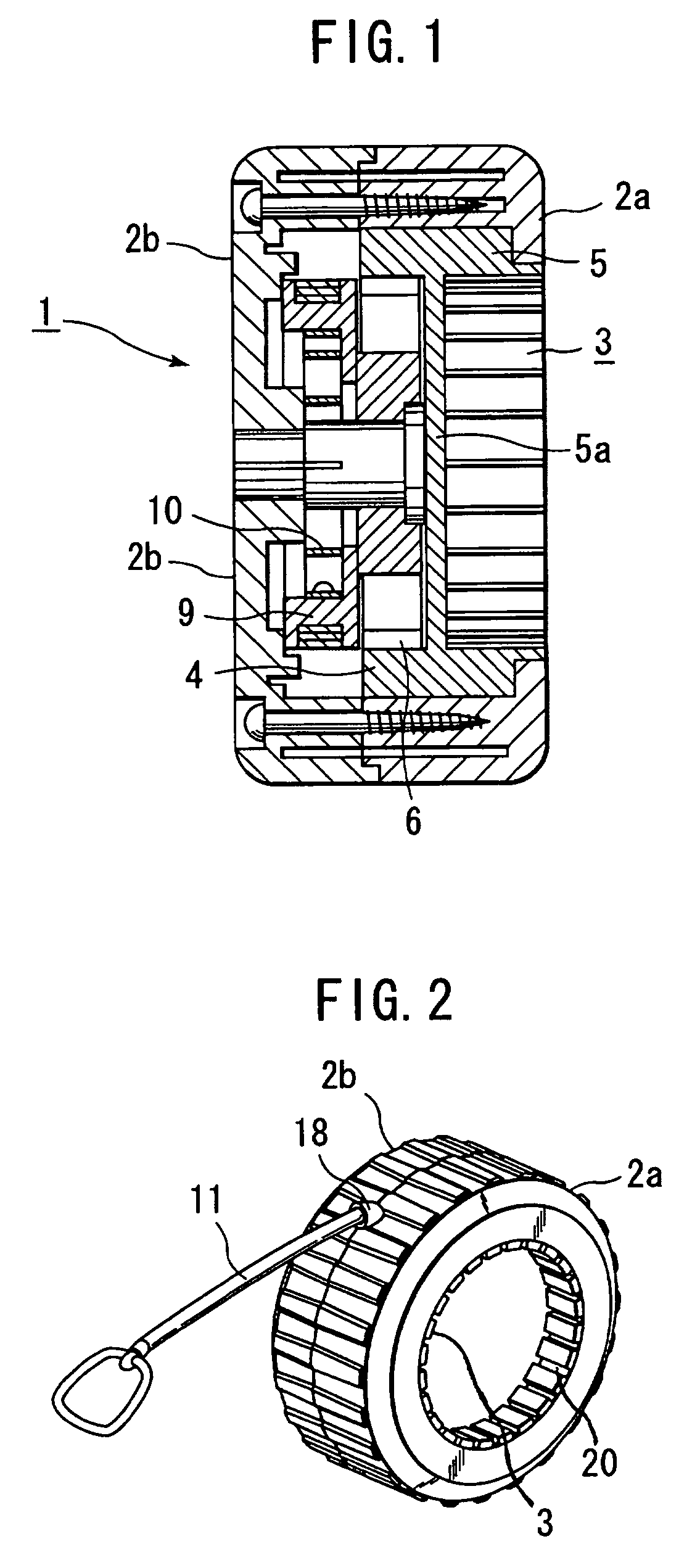
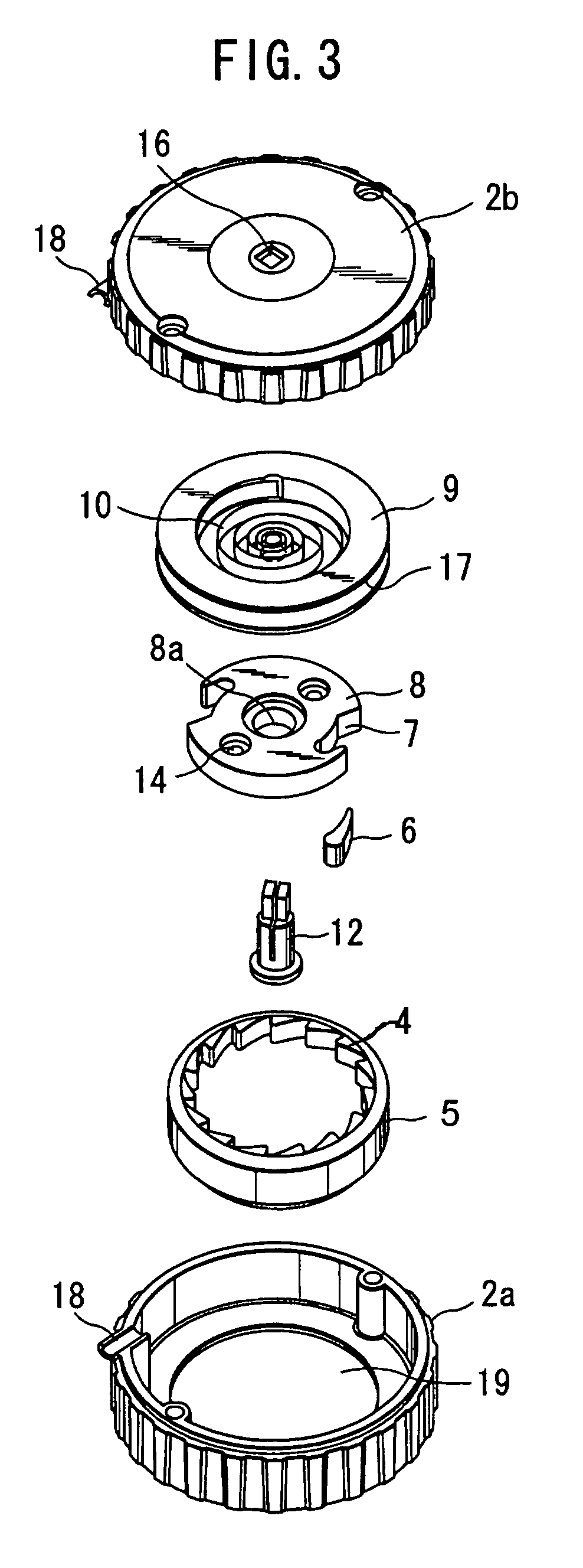
[0042]As shown in FIG. 1, a shoestring tying apparatus 1 shown in FIG. 1 includes a cover 2 (front cover 2a and back cover 2b) formed of colored resin for storing the internal configuration components thereof. The shoestring tying apparatus 1 further comprises a rotational member 5 having a configuration including a partition 5a, wherein a fitting portion 3 is formed on one side of the partition 5a for connecting to a fastening member 22 connected to a rotational cap 24 which is a conventional operating rotor or an outer rotational portion thereof with an internal gear 4 formed on the internal circumference on the other side of the partition 5a. The shoestring tying apparatus 1 also comprises a ratchet 8 including a pawl 6 at a pawl storage portion 7 for engaging with the internal gear 4, a spring storage member 9 which is in contact with the side of the ratchet 8, a helical spring 10 included in the spring storage member 9, an operating cord 11 connected to the spring storage memb...

second embodiment

[0063]Next, description will be made regarding a shoestring tying apparatus with reference to FIGS. 5 through 8.

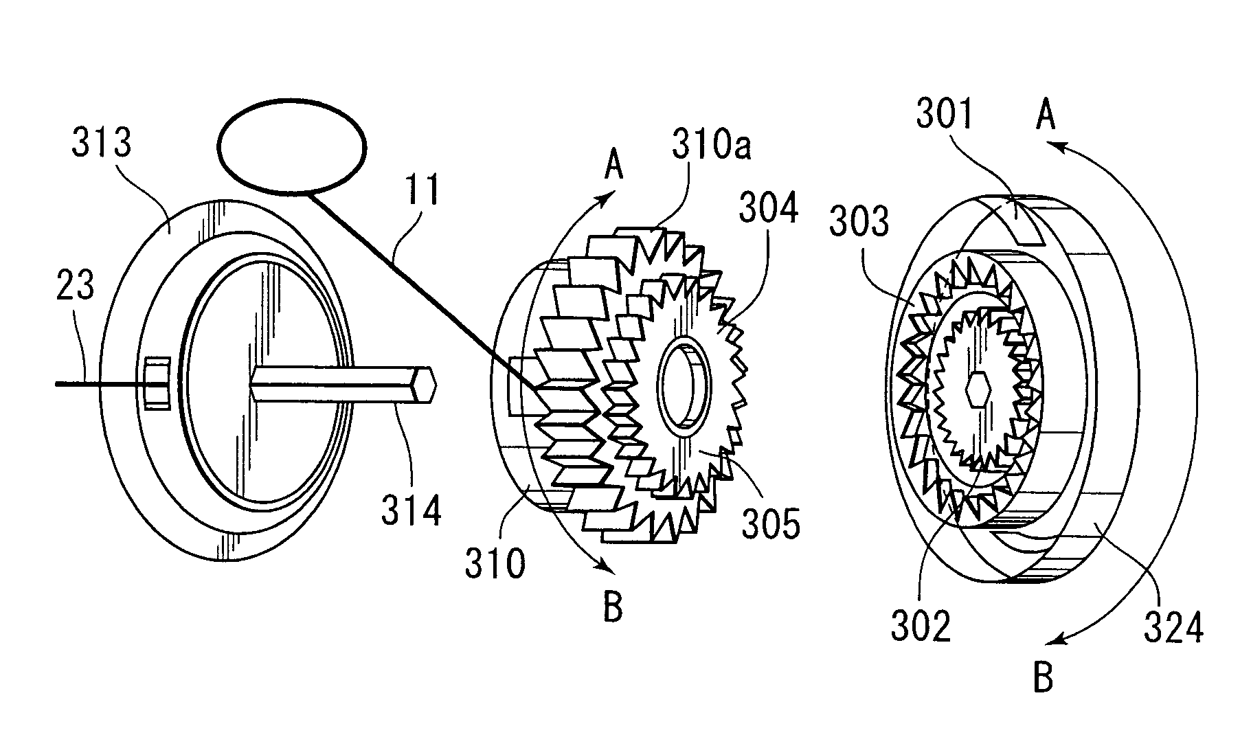
[0064]As shown in the drawings, a cap 324 includes multiple pawls 301 on the inner face thereof for engaging with a gear wheel so as to rotate in one direction, an internal gear 303 on the inner side of the pawls 301, and a gear wheel 302 on the inner side of the internal gear 303 for being moved within the cap 324. A hexagonal shaft 314 is fit to the gear wheel 302. Note that the cap 324 can be slidably moved along the hexagonal shaft 314.

[0065]On the other hand, a rotational member 305 includes an external gear 304 for engaging with the internal gear 303 of the cap 324, a spring therewithin for forcing the operating cord 11, and a shaft 312 which is rotatably fit to the aforementioned hexagonal shaft 314. The rotational member 305 further includes a ratchet 308 for engaging with the internal gear provided on the inner face thereof, and a cylinder 309 which is an interna...


PUM


Abstract

A fitting portion of a rotational member of a shoestring tying apparatus is fit to a rotational cap serving as an operating member of a fastening member for winding up and fastening a shoestring. The fitting portion serves as a connection between a driving mechanism and the rotational cap. When the user pulls an operating cord serving as a portion of a driving mechanism, a rotational member is rotated, and a spring included in the rotational member is wound. The rotational cap is rotated through the fitting portion due to rotation of the rotational member, thereby quickly rotating the fastening member. Thus, the fastening member can be rotated several dozen times by an operation in which the operating cord is alternately extracted and retracted several times. This provides a shoestring tying apparatus with excellent portability and appearance for easily and quickly fastening a shoestring in a sure manner.

Description

BACKGROUND OF THE INVENTION[0001]1. Field of the Invention[0002]The present invention relates to a shoestring tying apparatus for easily fastening a shoestring of a sport shoe or the like in a sure manner without using fastening tension by hand.[0003]2. Description of the Related Art[0004]Conventionally, a shoestring is laced through eyelets provided on the opening portion of a sport shoe or the like, and both ends of the shoestring are tied tightly at the ankle of the user. With athletic shoes, tension of the shoestrings is adjusted according to the required performance.[0005]Shoes such sport shoes including a disk for winding up a shoestring on the instep thereof are known. The ends of a shoestring, provided to the opening portion which can be opened for the user putting on or taking off the shoe, are fixed to the disk. Tension of the shoestring is adjusted according to the need of the user while winding the shoestring by rotating the disk in one direction, as disclosed in Japanes...

Claims


Application Information

Patent Timeline
Patent Type & Authority Patents(United States)
IPC IPC(8): A43C11/00A43C7/00A43C11/16
CPCA43C7/00A43C11/16A43C11/165Y10T24/3913Y10T24/2183
Inventor SAKABAYASHI, TOSHIKI
Owner SAKABAYASHI TOSHIKI
Why Eureka
Try Eureka