Control system with communication function and facility control system

a control system and communication function technology, applied in the field of control systems with communication functions and facility control systems, can solve the problems of difficult to update the correspondence between difficult to check whether or not received identification data and position data correctly correspond to one another, and inability to select devices as desired, so as to reduce costs.

Inactive Publication Date: 2006-07-18
KITZ CORP
View PDF20 Cites 19 Cited by
  • Summary
  • Abstract
  • Description
  • Claims
  • Application Information

AI Technical Summary

Benefits of technology

[0024]Still further, there is provided a facility control system comprising control units each of which controls devices and includes: a general output section to which the devices are connected; a memory storing a plurality of control patterns for controlling the devices; and a control pattern selector for selecting any of the control patterns for controlling devices. Therefore, it is possible to add, remove or change devices connected to the general output section at a reduced cost.
[0025]The facility control system further comprises a general input section to which optional devices are connected. The control pattern selector selects any of the control patterns for first devices connected to the general output section, and the control unit controls second devices connected thereto in accordance with control patterns selected in response to signals received from the devices connected to the general input section. Therefore, it is possible to add, remove or change devices connected to the general input section at a reduced cost.

Problems solved by technology

However, the foregoing control systems with the communication function are remote from devices to be monitored and managed, so that it is very difficult to check whether or not received identification data and position data correctly correspond to one another.
Further, it is difficult to update the correspondence between the identification data and position data when devices are added, removed or changed.
Therefore, it is not possible to select devices as desired, to restructure or to renew the control system.
In other words, convenient techniques have not been proposed up to now with respect to actual installation methods and operation of the facility control systems.
It is not possible to freely connect devices to the input and output terminals.
As a result, it is very difficult to add, remove or remodel devices, and it is expensive to reconstruct the facility control systems.

Method used


Image

  • Control system with communication function and facility control system
  • Control system with communication function and facility control system
  • Control system with communication function and facility control system

Examples


Embodiment Construction

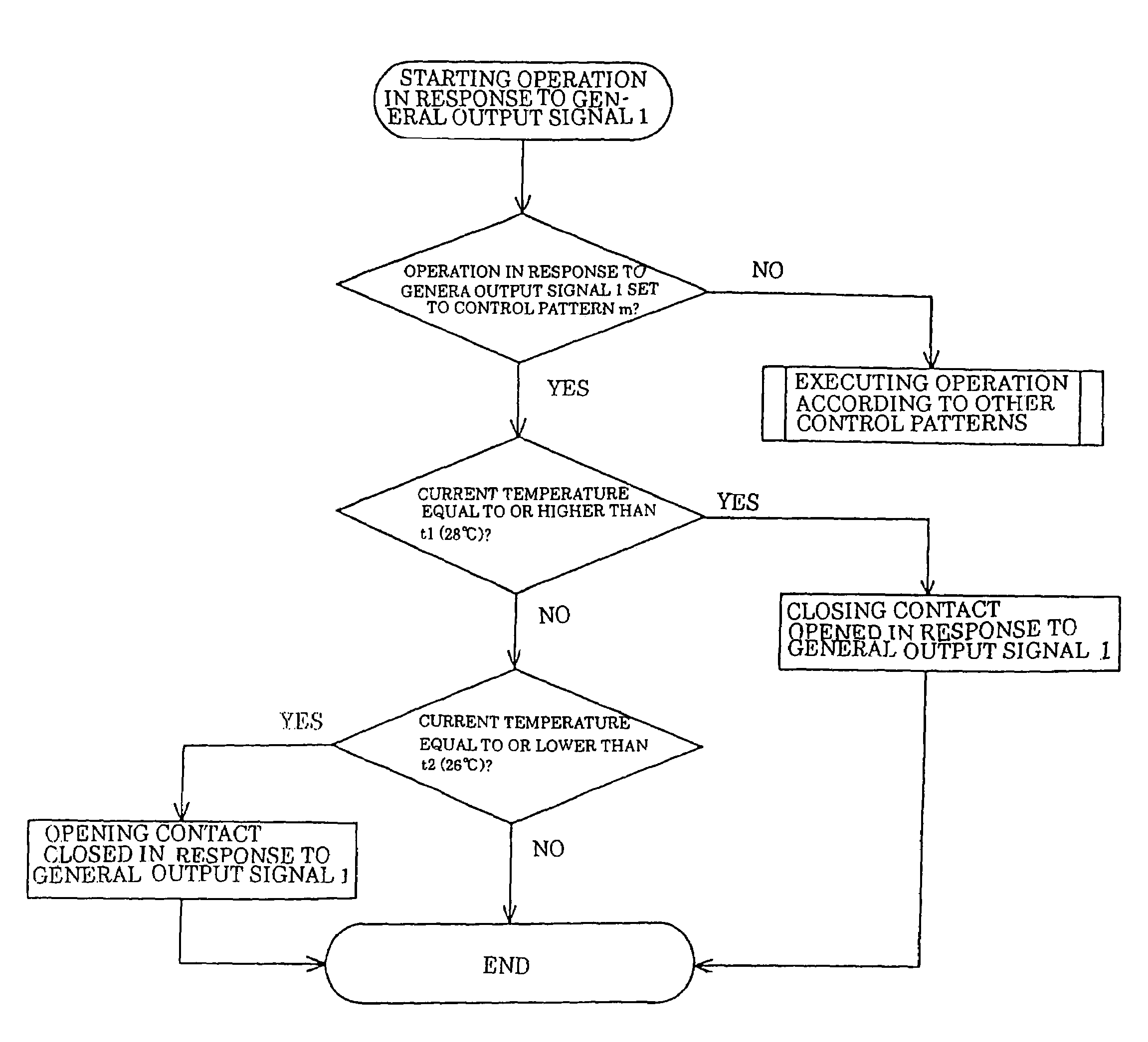
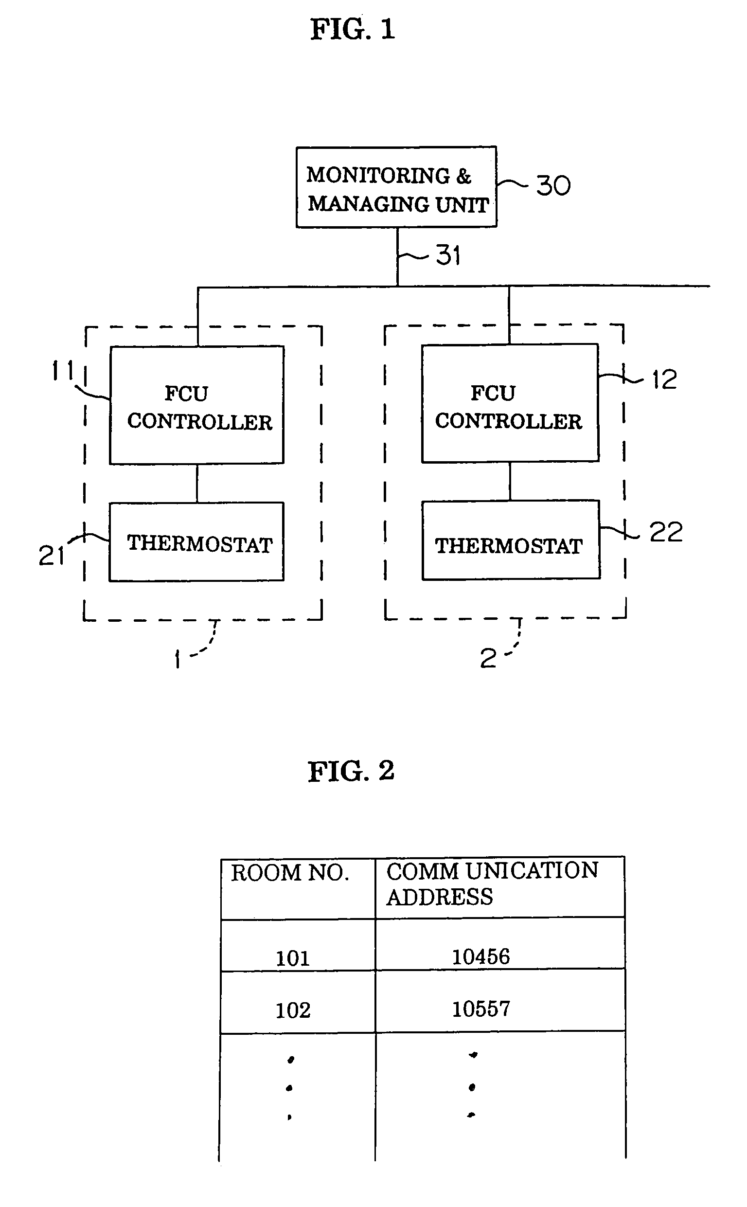
[0059]The invention will be described with reference to one embodiment shown in FIG. 1. In this embodiment, a control system with a communication function is used to manage facilities in a building. Rooms 1, 2, . . . are provided with facility control units, i.e. fan coil unit controllers (called “FCU controllers”) 11, 12 . . . and thermostats 21, 22. The thermostats 21, 22 . . . are used to set room temperatures, and the FCU controllers 11, 12 . . . control the temperatures of individual rooms 1, 2, . . . in order to cool or heat them or blow air to them.

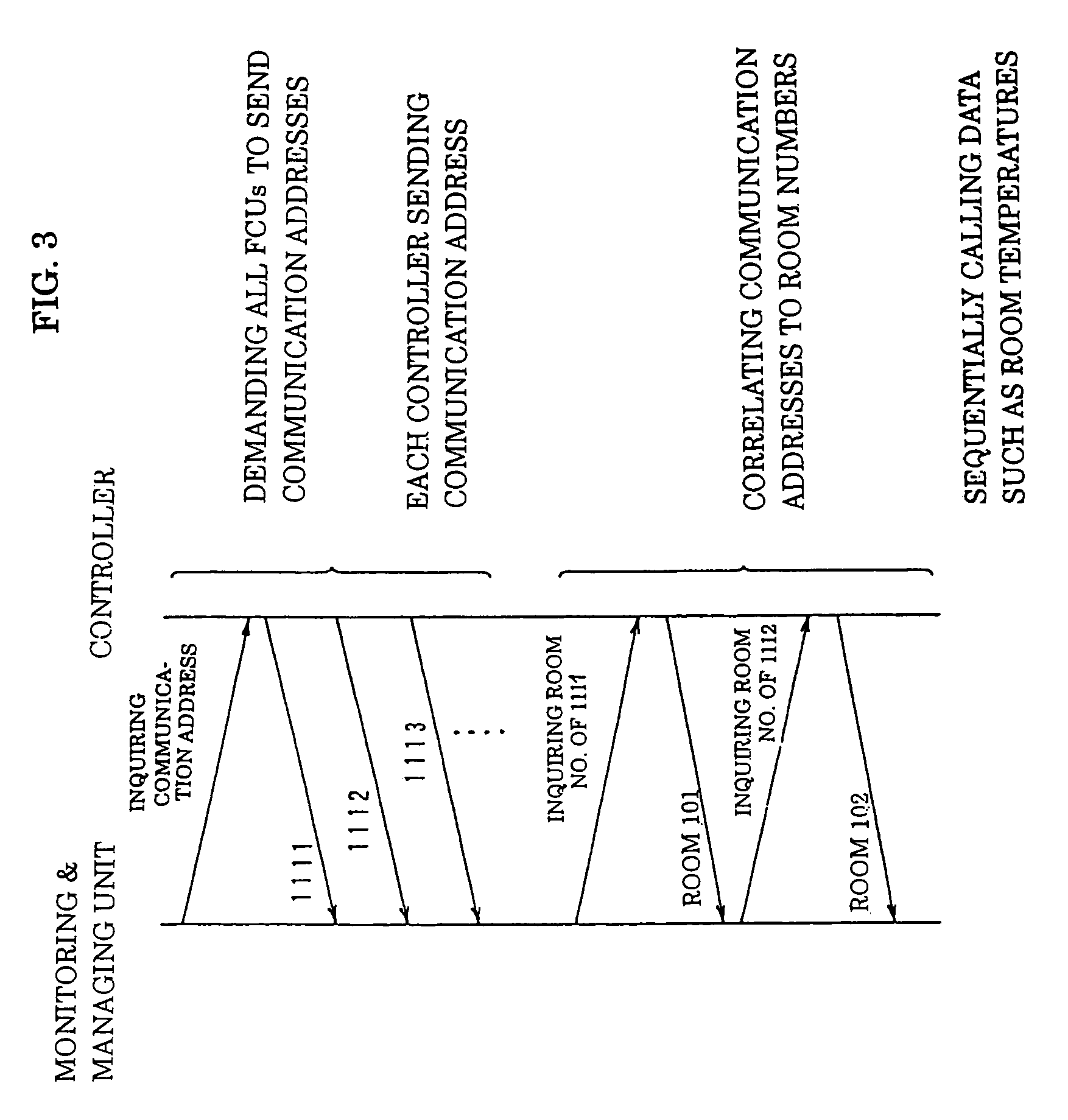
[0060]A monitoring and managing unit 30 as a central control unit is connected to, communicates with and controls the FCU controllers 11, 12, . . . via a network 31, thereby monitoring and managing the operations of air-conditioners and so on in the rooms 1, 2.

[0061]The thermostats 21, 22 . . . are also used to input room numbers as position data peculiar to the FCU controllers 11, 12 . . . . The FCU controllers 11, 12 . . . store ...


PUM


Abstract

A control system with a communication function wherein: a central unit communicates 30 with a plurality of devices 11, 12, . . . , monitors and manages the operations of the devices; and each of the devices includes an input section for entering position data thereof. The central unit receives the position data and an identification data of each device, and includes a unit for making the identification data correspond to the position data for each device.

Description

[0001]This application is a Division of application Ser. No. 10 / 070,451 filed on Mar. 20, 2002 now U.S. Pat. No. 6,736,328.FIELD OF THE INVENTION[0002]The present invention relates to a control system with a communication function in which a central unit communicates with a plurality of devices in order to monitor or manage their operations, and a facility control system for managing the operation of air conditioners and so on.DESCRIPTION OF THE RELATED ART[0003]In a control system with a communication function, a central unit including a central monitoring and / or managing device communicates with various devices in order to monitor or manage their operations. Usually, the devices have their own identification data such as communication addresses in order to communicate with the central unit. The central unit detects a particular device on the basis of position data (e.g. a room number) of a room where the device is installed. Therefore, there should be the correspondence between th...

Claims


Application Information

Patent Timeline
Patent Type & Authority Patents(United States)
IPC IPC(8): F25B49/00F24F11/00
CPCF24F11/0009F24F11/006F24F11/0012F24F11/0034F24F2011/0068F24F2003/1667F24F2011/0067F24F11/30F24F2110/10F24F2120/10F24F11/62F24F11/54F24F11/56F24F8/22F24F11/63
Inventor TAKUSAGAWA, MASARU
Owner KITZ CORP
Why Eureka
Try Eureka