Tire pressure monitoring system

a technology of tire pressure monitoring and monitoring system, which is applied in the direction of tire measurement, vehicle components, transportation and packaging, etc., can solve the problems of not knowing the prior art devices alone or even in combination, and prone to leakage and different behavior of batteries, so as to promote and enhance safety and prevent accidents.

Inactive Publication Date: 2006-07-18
KNOX LEWIS LEE
View PDF6 Cites 21 Cited by
  • Summary
  • Abstract
  • Description
  • Claims
  • Application Information

AI Technical Summary

Benefits of technology

[0020]8. Another objective of this invention is that the invention use modular standard components easily interface-able to each other.
[0023]11. Another objective of this invention is that it promote and enhance safety by preventing accidents due to under or over inflated tires and further that it be physically safe in normal environment as well as accidental situations.
[0028]Other objectives of this invention reside in its simplicity, elegance of design, ease of manufacture, service and use and even aesthetics as will become apparent from the following brief description of the drawings and the detailed description of the concept embodiment.

Problems solved by technology

Batteries are prone to leakage and behave differently depending on the temperature.
Radio transmissions are subject to interference and must meet FCC regulations.
Unfortunately none of the prior art devices know to the applicants or their attorney singly or even in combination provide for all of the objectives as established by the inventor for this system as enumerated below.
This obviates the problem of local battery leakage and / or periodic replacement.

Method used


Image

  • Tire pressure monitoring system
  • Tire pressure monitoring system
  • Tire pressure monitoring system

Examples


Embodiment Construction

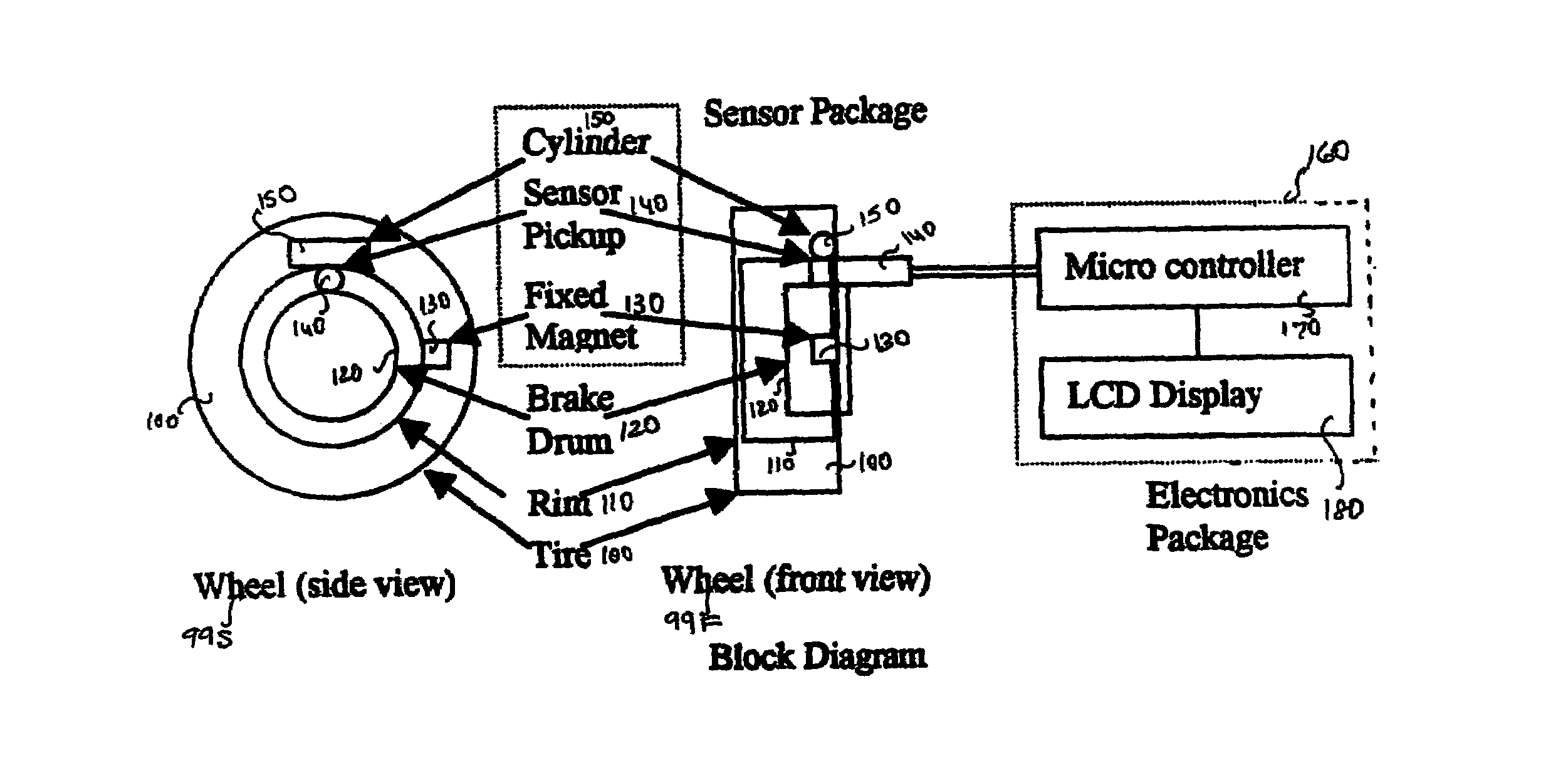
[0037]The continuous real time tire pressure monitoring system of this invention as shown in the various drawings wherein like numerals represent like parts throughout the several views, there is generally disclosed in FIG. 1 is a Block Diagram of the tire pressure monitoring system of this invention complete with Front view of a wheel 99-F, Side view of a wheel 99-S, Tire generally 100, Rim 110, Brake Drum 120, Fixed Magnet 130. Sensor Transducer 140, Cylinder 150, Electronics module 160, Microcontroller including a microprocessor 170 and Liquid Crystal or comparable display device 180.

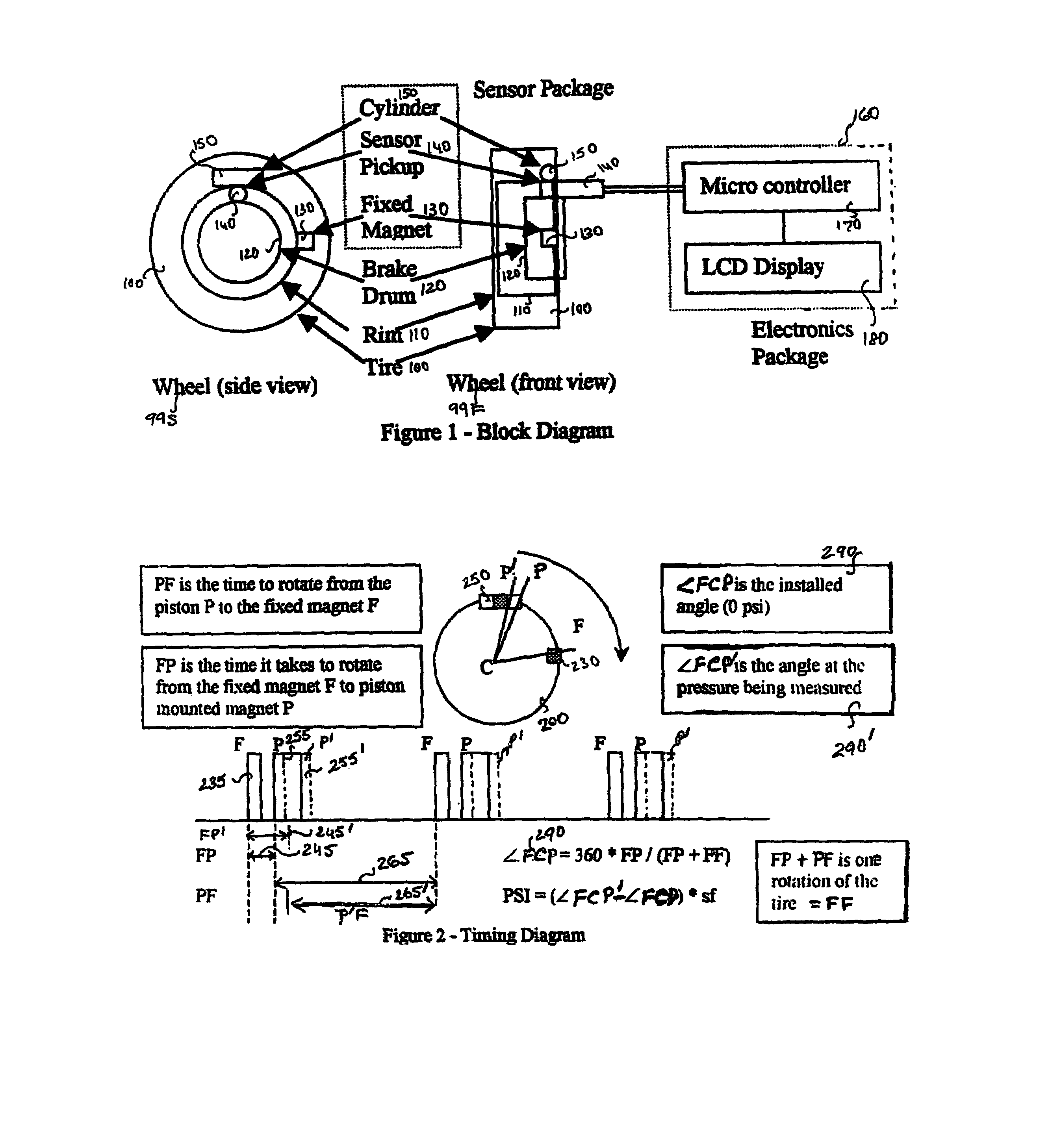
[0038]The air pressure is measured by the displacement of a piston 140 in a cylinder 150. By attaching a magnet to the piston in the air cylinder a magnetic field is generated around the piston. The reference point for computation may be obtained by vertically aligning piston to the center of the magnetic field, and or a horizontally aligned piston a separate reference magnet. The displacement of the...


PUM


Abstract

A System of monitoring the air pressure in the tires of a moving vehicle continuously in real time for measuring the pressure in a rotating tire and transmitting the information via magnetic pulses to a sensor pickup located near the tire, but on a non-rotating part of the vehicle, for transmittal via wire to a micro controller for conversion to air pressure units and display. It comprises a sensor module for each wheel, and an electronics module in the passenger compartment. It computes the air pressure by measuring the phase angle between a fixed magnet and a magnet placed on a piston in an air cylinder within the tire.

Description

RELATED APPLICATIONS[0001]This application is a Continuation-In-Part application to non-provisional application Ser. No. 10 / 073,575 filed Feb. 12, 2002 now abandoned which in turn was a Continuation-In-Part application to non-provisional application Ser. No. 09 / 753,391 filed Jan. 4, 2001 now abandoned claiming priority from provisional application Ser. No. 60 / 260,657 filed Jan. 11, 2001 all of which are based on and relate to Disclosure Document Number 450,235 dated Jan. 25, 1999 then entitled Computerized Air Pressure System invented by Lewis Knox.BACKGROUND[0002]This invention relates generally to motor vehicle safety by continuously monitoring the tire pressure in real time so as to prevent accidents caused by over or under inflated tires. More particularly it relates to a system for the transmission of air pressure information from inside a rotating tire to the non-rotating portion of a tire of motor vehicle, from whence it can be displayed. Such a system must of necessity emplo...

Claims


Application Information

Patent Timeline
Patent Type & Authority Patents(United States)
IPC IPC(8): B60C23/02
CPCB60C23/0425
Inventor KNOX, LEWIS LEE
Owner KNOX LEWIS LEE
Why Eureka
Try Eureka