Vehicle suspension system

a suspension system and vehicle technology, applied in the direction of springs/dampers, mechanical equipment, transportation and packaging, etc., can solve the problems of sacrificed, achieve the effect of reducing torque on the axle, and reducing the risk of slipping

Inactive Publication Date: 2006-07-18
HOLLAND BINKLEY +1
View PDF37 Cites 53 Cited by
  • Summary
  • Abstract
  • Description
  • Claims
  • Application Information

AI Technical Summary

Benefits of technology

[0003]The suspension of the present invention is an improvement which is intended to meet most if not all the aforementioned objectives. The suspension provides a high degree of roll stability and, in some embodiments, substantially eliminates dock walk. The suspension is designed to reduce torque on the axle to increase axle life, and in general has components of greater durability. The suspension provides a soft ride performance equal to or better than existing air systems. In some embodiments the suspension provides load equalization under braking so only one of the two axles requires ABS sensors. The suspension is equipped for easy axle alignment, either at the factory or in the field. The suspension can be used as a tandem road trailer unit without modification. The system is light in weight and can be fabricated at low cost. Further, the suspension can be used with existing trailers and axle and brake systems. The suspension is also designed to reduce axle stress so that the axles of the suspension can be made of lighter material, if desired.
[0006]Another aspect of this invention is directed to a bushing assembly for a pivot connection between a vehicle frame and axle-supporting beam of a vehicle suspension to permit pivoting of the beam relative to the frame. The bushing assembly comprises an inner metal sleeve having a central longitudinal axis about which the beam is adapted to pivot, and a resilient annular bushing member of resilient material surrounding the inner metal sleeve. The bushing member has a radial inner surface adjacent the inner metal sleeve and an opposite radial outer surface. An outer metal sleeve surrounds the bushing member, the outer metal sleeve having a radial inner surface adjacent the bushing member and an opposite radial outer surface. The outer surface of the resilient bushing member is relieved in a radially inward direction toward said central longitudinal axis to facilitate deflection of the bushing member in said radially inward direction.

Problems solved by technology

While certain prior designs have achieved some of these objectives, it has been usually been at the sacrifice of other objectives.

Method used


Image

  • Vehicle suspension system
  • Vehicle suspension system
  • Vehicle suspension system

Examples


Embodiment Construction

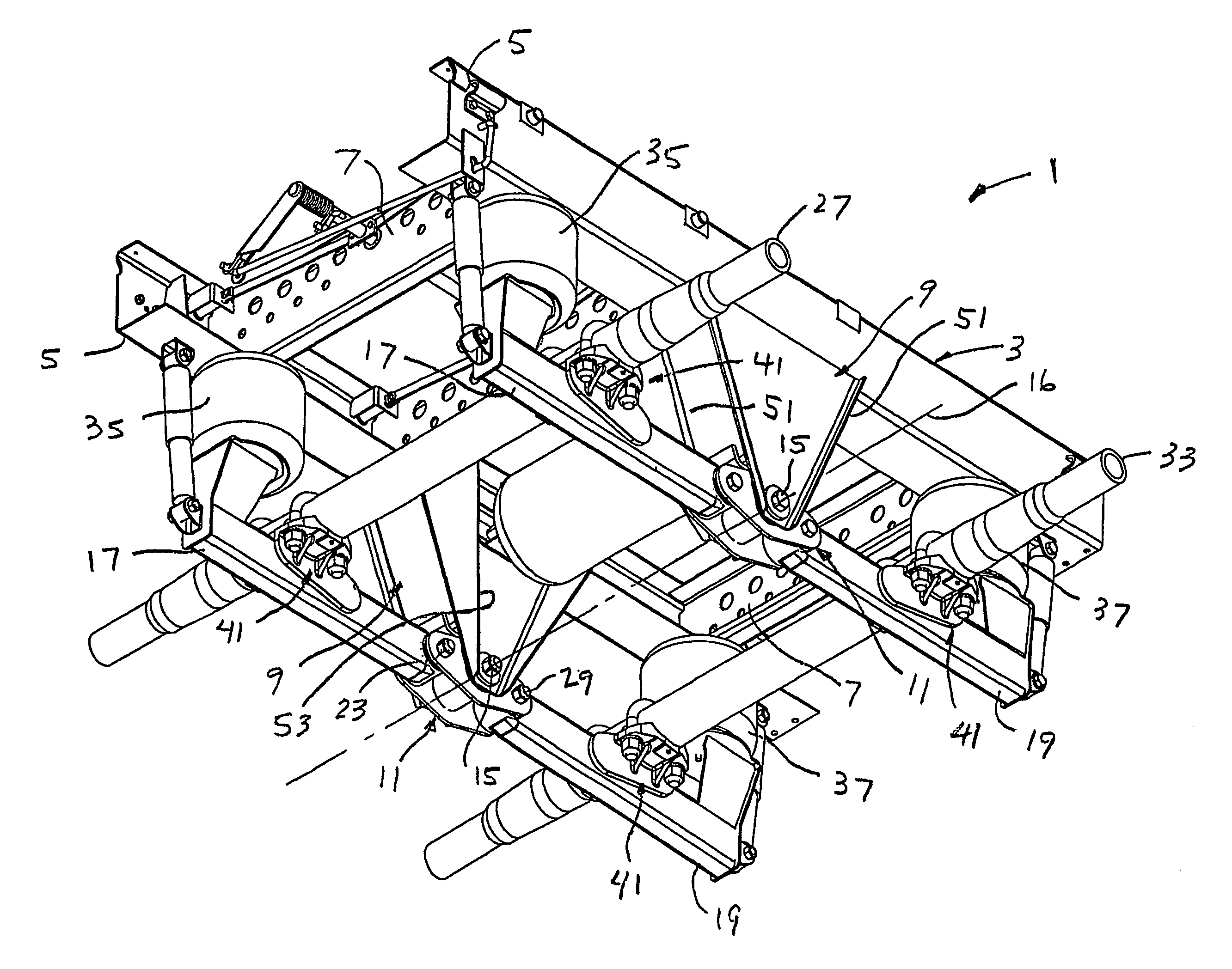
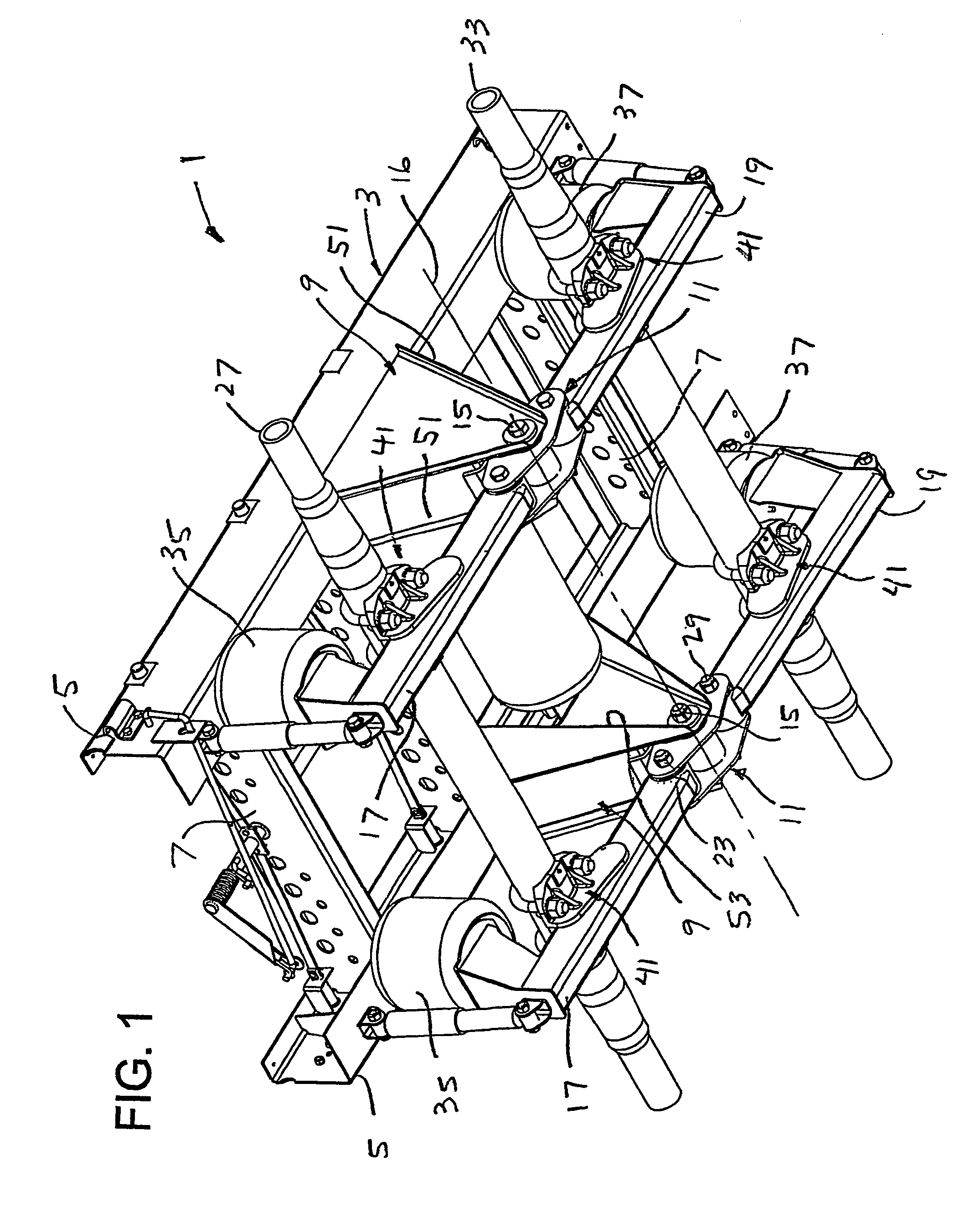
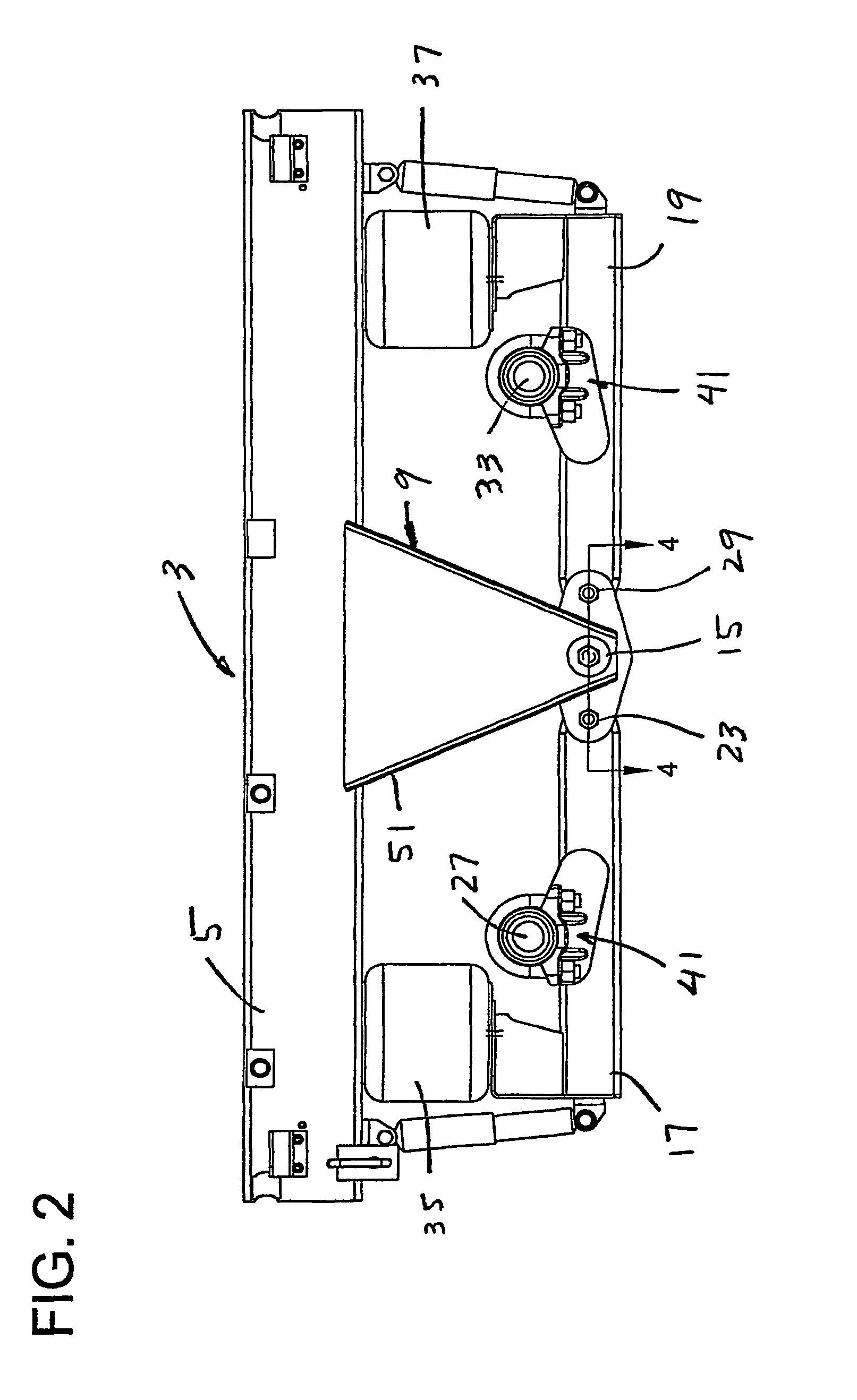
[0055]Referring now to FIGS. 1–4 of the drawings, a vehicle suspension of the present invention is designated in its entirety the reference numeral 1. As shown, the suspension is a slider of the type which is affixed to the frame of truck. However, it will be understood that the present invention has applications to vehicle suspensions generally.

[0056]The suspension comprises a frame 3 which includes a pair of parallel rails 5 connected by cross members 7, and hangers 9 depending from the rails 5 at opposite sides of the frame generally midway between the ends of the rails. The frame has forward and rearward ends, the forward end being the left end as viewed in FIG. 1 and the rearward end being the opposite (right) end. In accordance with one aspect of the present invention, the frame further comprises a pair of levers 11, referred to as equalizers, one at one side of the frame 3 and the other at the other side of the frame. Each lever 11 (comprising two parallel bars 11a, 11b in th...


PUM


Abstract

A vehicle suspension comprising a frame (3) and a pair of levers (11) carried by the frame on opposite sides thereof. Each lever is pivotally mounted on the frame for swinging movement on an axis intermediate opposite ends of the lever transverse to the frame. The suspension includes a pair of beams (17, 19), one extending forward from one of the levers and the other extending forward from the other lever, each of the forwardly-extending beams having a pivotal connection with the respective lever forward of the lever axis and having a support for a forward axle. The suspension also includes a pair of beams, one extending rearward from the other lever, each of said rearwardly-extending beams having a pivotal connection with the respective lever rearward of the lever axis and having a support for a rearward axle.

Description

BACKGROUND OF THE INVENTION[0001]This invention relates generally to vehicle suspensions, and more particularly to an improved suspension for tandem-axle trucks.[0002]The present invention is especially suited for beam-type suspensions where the axles of a tandem-axle truck are supported by beams pivoted to hangers on opposite sides of the frame of the truck. Springs (e.g., air bags) on the axle ends of the beams support the frame. Ideally, such suspensions are designed to be as lightweight as possible, to provide a soft ride and adequate roll stiffness or stability, that is, resistance to the tendency of the truck body to roll laterally during cornering, to provide an even distribution of the load over the wheels as the truck travels over bumps and as it turns, to provide good braking, to minimize torque applied to the axle as the vehicle encounters bumps in the road, and as it turns, and to eliminate so-called “dock walk”, which is the tendency of a vehicle to move away from a doc...

Claims


Application Information

Patent Timeline
Patent Type & Authority Patents(United States)
IPC IPC(8): B60G3/12B60G5/02B60G7/00B60G7/02B60G9/00B60G11/28F16F1/38
CPCB60G5/02F16F1/38B60G7/02B60G9/003B60G11/28B60G7/001B60G2200/31B60G2200/318B60G2202/152B60G2204/126B60G2204/128B60G2204/129B60G2204/143B60G2204/148B60G2204/41B60G2204/416B60G2204/421B60G2204/4302B60G2204/4306B60G2204/44B60G2206/11B60G2206/601B60G2206/8201B60G2206/8207B60G2300/0262
Inventor PETERS, SCOTT R.BAXTER, BOB G.TOMIC, ZORAN
Owner HOLLAND BINKLEY
Why Eureka
Try Eureka