Circular connector assembly

a technology of connectors and connector parts, applied in the direction of coupling device connections, coupling parts engagement/disengagement, incorrect coupling prevention, etc., can solve the problems of not being sure of the fitting condition of the male and female connectors of the assembly, and the low reliability of the circular connector assembly b>70/b>, so as to prevent accidental release of an engagement between the locking hook and the detector, the reliability of the engagement between the male and female connectors is further improved

Active Publication Date: 2006-07-18
YAZAKI CORP
View PDF8 Cites 19 Cited by
  • Summary
  • Abstract
  • Description
  • Claims
  • Application Information

AI Technical Summary

Benefits of technology

[0020]According to the above, after the male and female connectors are initially and shallowly engaged with each other, as the engaging ring is rotated, the male and female connectors are shifted in a direction of engaging the connectors with each other, and engaged deeply with each other. When the connectors are fully engaged with each other, the resilient locking arm of the engaging ring is engaged with the detector to prevent the engaging ring from rotating in a reverse direction. Since the resilient locking arm is a free end extending along a radial direction, the resilient locking arm is prevented from being bent or twisted. Further, the resilient locking arm is prevented from projecting outward in a radial direction. Thereby, the connector assembly is prevented from being upsized, and is adapted for a downsized engine room and the like.
[0032]According to the above, when the engaging ring is rotated in a reverse direction, the resilient locking arm is drawn inwardly in a radial direction of the one connector. Thereby, the locking hook and the detector is engaged further. Therefore, an accidental release of an engagement between the locking hook and the detector is prevented, and the reliability of the engagement between the male and female connectors is further improved.

Problems solved by technology

However, there are problems as described below in the conventional circular connector assemblies.
Thus, reliability of the circular connector assembly 70 is not high.
Regarding the third embodiment of the circular connector assembly, there is a problem similar to the first embodiment that the fitting condition of the male and female connectors of the assembly is not detected surely, and sometimes a half-fitting condition of the connectors is mistaken for a fully fitting condition.

Method used


Image

  • Circular connector assembly
  • Circular connector assembly
  • Circular connector assembly

Examples


Embodiment Construction

[0043]An embodiment of a circular connector assembly according to this invention will be explained below with reference to Figures.

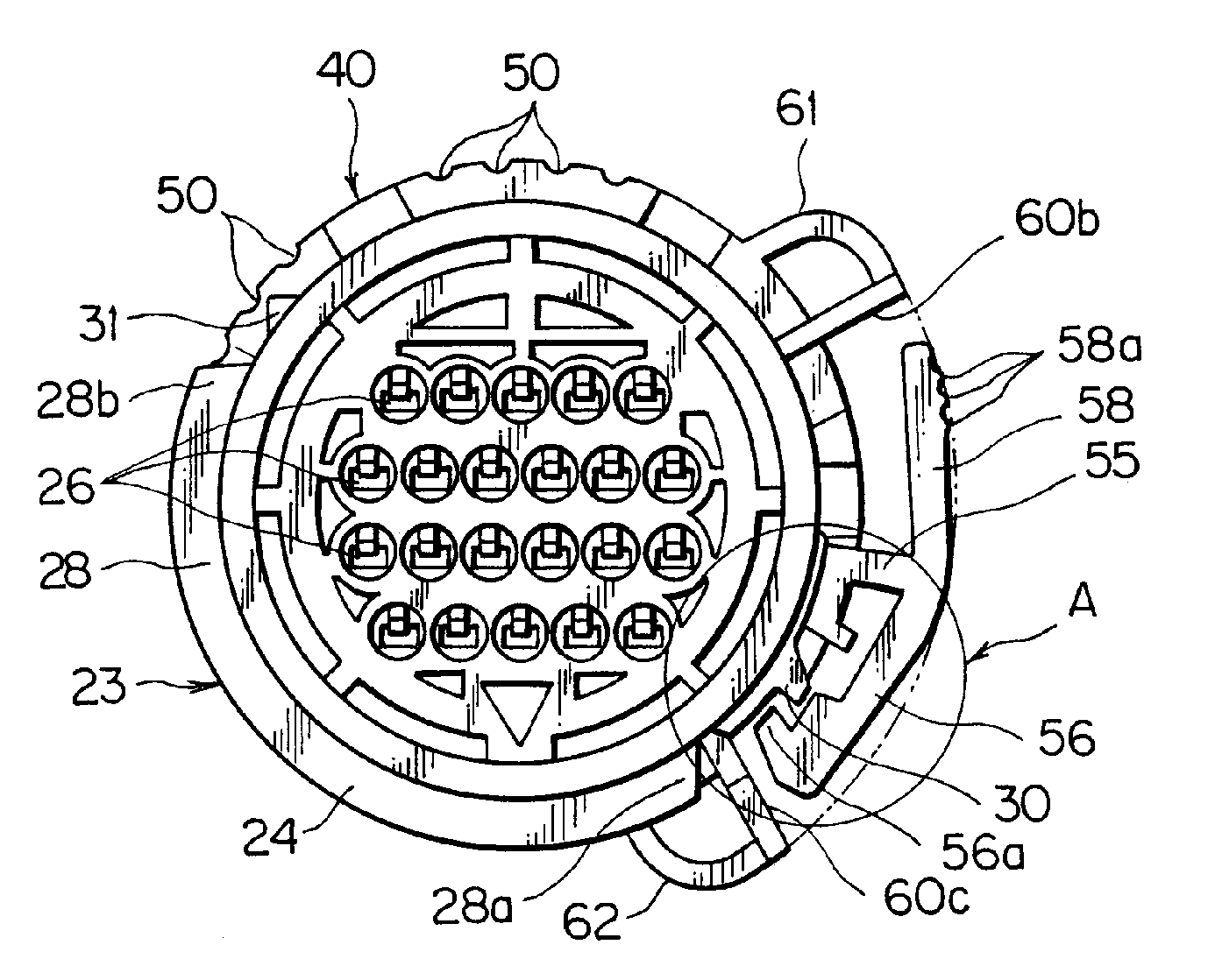
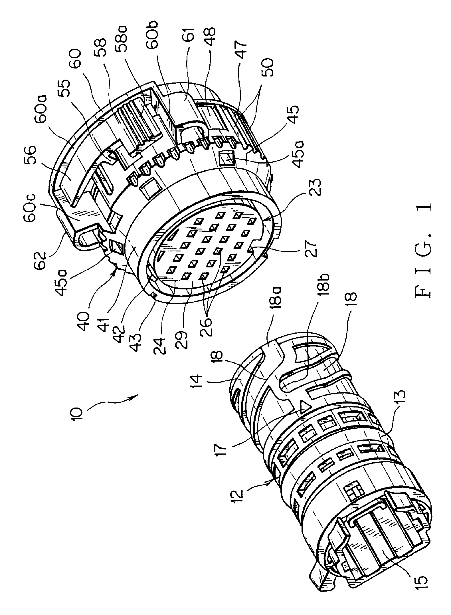
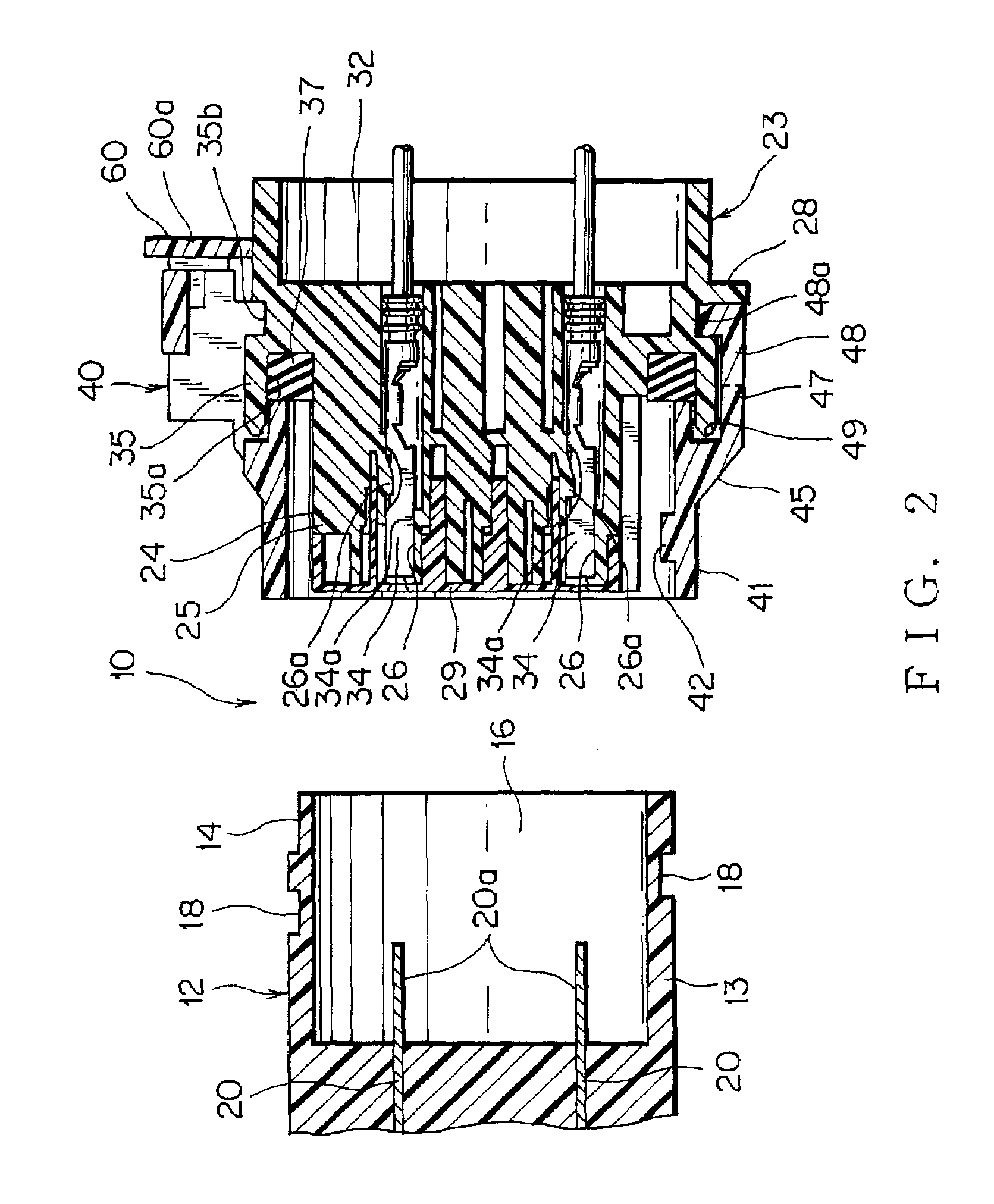
[0044]A circular connector assembly 10 is used as a transmission of a vehicle and the like. Male and female multiway connectors 23, 12 are engaged with each other through an engaging ring 40. An engagement between the male and female connectors electrically connects male and female terminals 20, 34 in twenty-two ways to supply signal currents from such as an Electronic Control Unit (ECU).

[0045]The circular connector assembly 10 of this embodiment allows to recognize a full engaging state of the male and female connectors 23, 12 visually, aurally, and by a feel of a rotation of the engaging ring 40. Therefore, engaging reliability between the male and female connectors 23, 12 is improved. A temporary locking projection 31 for mounting the engaging ring 40 at a reference position for assembly, and a detecting locking projection (detector) 30 positioned for...


PUM


Abstract

A temporary locking projection for mounting the engaging ring at a reference position for assembly, and a detecting locking projection positioned forward of the temporary locking projection in a rotating direction of the engaging ring are provided on an outer periphery of the male connector housing and projected outward in a radial direction thereof. A temporary locking wall extending in an axial direction of the engaging ring for engaging with the temporary locking projection, and a resilient locking arm having a locking hook at an inner distal end surface are provided on an outer surface of the engaging ring. The locking hook is engaged with the detecting locking projection. A contact surface for contacting the resilient locking arm is provided at a projecting end of the detecting locking projection. A step having a contact surface for contacting the contact surface of the detecting locking projection is provided on the resilient locking arm.

Description

BACKGROUND OF THE INVENTION[0001]The priority application Number Japanese Patent Application 2004-075767 upon which this patent application is based is hereby incorporated by reference.[0002]1. Field of the Invention[0003]This invention relates to a circular connector assembly, of which male and female connectors are electrically connected to each other via an engaging ring for use in, for example, a transmission of a vehicle.[0004]2. Description of the Related Art[0005]As shown in FIGS. 8 and 9, Japanese published unexamined patent applications No. Hei 04-132178 (pages 4 to 6, FIG. 1) and Hei 10-154553 (page 3 to 5, FIG. 1) disclose first and second embodiments of conventional circular connector assemblies 70 in FIG. 8, 80 in FIG. 9. The circular connector assembly 70 is a multipin connector assembly accommodating a plurality of terminals 72, 74. A male and female connectors 71, 73 of the circular assembly 70 are connected to each other by rotating an engaging ring 76. Generally, f...

Claims


Application Information

Patent Timeline
Patent Type & Authority Patents(United States)
IPC IPC(8): H01R13/62H01R13/213H01R13/623H01R13/639H01R13/64H01R13/641H05K13/00
CPCH01R13/623H01R13/641
Inventor SANUKI, HIDENORI
Owner YAZAKI CORP
Why Eureka
Try Eureka